Positioning of Elements
The objects describing the scenario must be positioned relative to one another. This can be defined via x-y-z-coordinates in the coordinate system. As this can be complicated, MASC generates the coordinates automatically after requesting some simple parameters from the user. All user entered values are values relative to the border of the wall, mast or arm.
Arms (At Masts)

Figure 1. Top view of real and modeled mast including the inner circle of the modeled mast (and four arms).
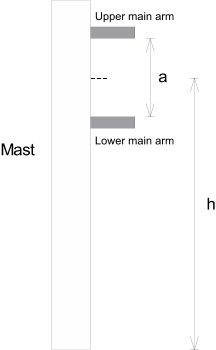
Figure 2. Vertical positioning of arms at the mast.
Arms (At Walls)
Both arms are horizontal and orthogonal to the wall. You can define the distance between the arms and the distance of the arms from the borders of the wall.
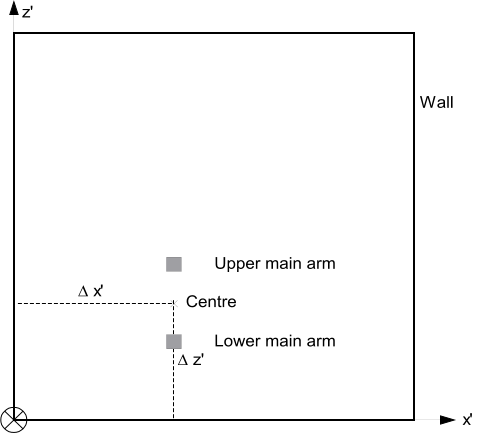
Figure 3. Positioning of the arms on the wall.
Tube (Vertical)
The vertical tube is always fixed in front of the two arms. Its vertical center is on the height exactly between the two arms.
Sub-Arms
Sub-arms are optional. If they are used, they are always fixed at the tube. Similar to the arms, the distance between the sub-arms is also user defined. The sub-arms are vertically centered to the tube. Their azimuth orientation is defined by the user and is similar to the azimuth of the antenna itself.
Radome
Omni, as well as sector radomes (for example, circular and rectangular cross-section), are mounted directly at the sub-arms (if used) or at the tube (if no sub-arms are used).