MV-8050: Leaf Spring Builder
In this tutorial, you will learn how to access the Leaf Spring Builder utility, populate a leaf spring model with data, save the data, generate a MotionView file of the leaf spring, open the model in MotionView, create a test of the model, and exercise the test using the utility.
The purpose of this tutorial is to introduce you to the Leaf Spring Builder utility.
The Leaf Spring Builder is a utility designed to work with MotionView and the vehicle modeling libraries included with MotionView. Spring geometry, bushing rates and a number of other physical constants are required as input to the model. Reasonable defaults for data are included for many fields, which will make the model run. Accurate data should be substituted as it becomes available. The output of the utility is a beam and mass model of a leaf spring, in either a MotionView system definition file or a complete MotionView model.
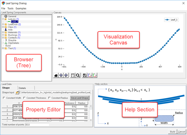
Figure 1.
- Browser: Used for navigating and selecting leaf spring components.
- Property Editor: Used for entering and modifying data.
- Help Section: Used for describing the data you enter.
- Visualization Canvas: Used for viewing leaf shapes. When you select data in the browser the leaf spring builder displays the corresponding editor, visualization canvas and help section.
To learn more about the Leaf Spring Builder, see the Leaf Spring Modeling topic.
Access the Leaf Spring Builder
In this step, you will load the MBD-Vehicle Dynamics Tools preference file in MotionView and display the leaf spring builder.
| File Name | File |
|---|---|
| Comma Separated Values files | Leaf_1.csv |
| Leaf_2.csv | |
| Leaf_3.csv | |
| Leaf_4.csv |
The .csv files used in this tutorial contain coordinate pairs that represent the geometry of the centerline of the leaf. The leaf in this tutorial was created by measuring geometry from a light truck rear suspension. The rear suspension in this example has a GAWR of 3950 lbs.
To build a leaf spring model, you must first load the MBD-Vehicle Dynamics Tools preference file in MotionView. Once loaded, HyperWorks remembers and automatically loads the MBD-Vehicle Dynamics Tools preference file each time you start HyperWorks.
-
Launch MotionView.
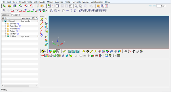 Figure 2.
 -
From the menu bar, click .
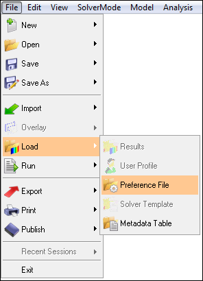 Figure 3. The Preferences dialog opens.
 -
From the Preferences dialog, select MBD-Vehicle
Dynamics Tools and click Load.
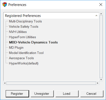 Figure 4. The vehicle dynamics tools preference file is loaded.
 -
From the menu bar, click .
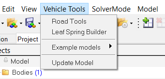 Figure 5. The Leaf Spring dialog opens.
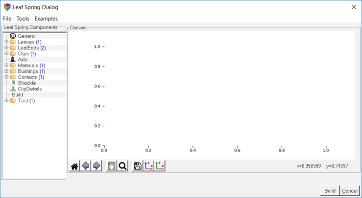 Figure 6.
Select Primary Systems
In this step, you will select the primary systems using the General component of the Leaf Spring dialog.
-
From the Leaf Spring Components browser section, click
General.
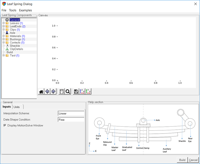
Figure 7.The leaf model is displayed in the Help section of the dialog. -
Select the primary systems as indicated in Figure 8.
- Select Linear from the Interpolation Scheme drop-down menu.
- Select Pre-Assembly from the Data Shape Condition drop-down menu.
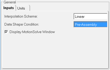
Figure 8.Note: Default units are set in the Units tab of the General component.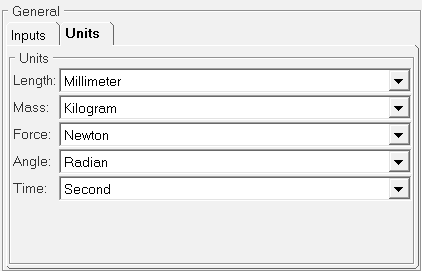
Figure 9.
Add Leaf Components
In this step, you will add leaf components within the Leaf Spring Components browser section.
Leaves components allow you to add leaves to the leaf spring.
-
From the Leaf Spring Components browser section, right-click the
Leaves component and select Add a
Leaf.
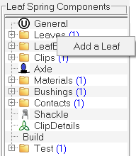
Figure 10.A leaf 2 component is added to the leaves component. -
Repeat step 1
twice to add two additional leaves to the Leaves component.
The Leaves component should contain four leaf components as indicated in Figure 11.
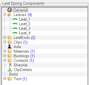
Figure 11.
Enter Leaf 1 Data
In this step, you will enter the required data for Leaf 1 using the Leaf Data section.
-
From the Leaf Spring Components browser section, click the Leaf
1 component.
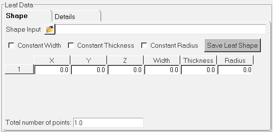
Figure 12. -
From the Leaf Data section, browse and select the
Leaf_1.csv file for the Shape Input field.
You can also specify the required values for the X coordinate, Z coordinate and width and thickness variation manually for the leaf profile.Tip: If the leaf is a constant thickness (and/or width), you need to specify the values only in the first row. The same value will be used along the entire length of the leaf.
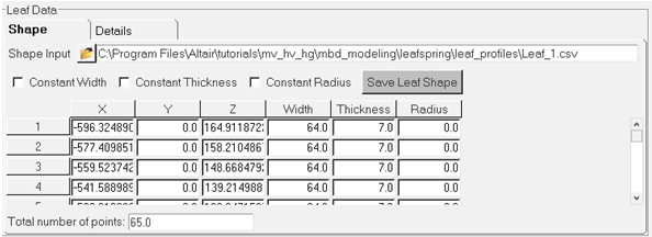
Figure 13.The Leaf 1 graphics are displayed in the Canvas section.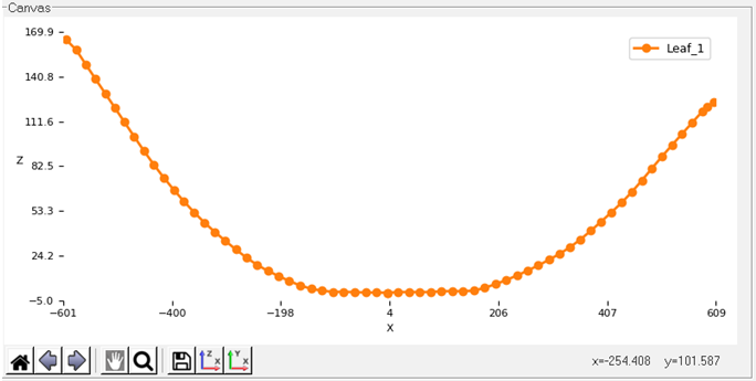
Figure 14. -
Enter the required Leaf 1 data as indicated in Figure 15.
- For Front Leaf Length, enter 596.325.
- For Rear Leaf Length, enter 604.14.
- For No. of Beams in front, enter 15.
- For No. of Beams in rear, enter 15.
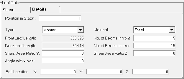
Figure 15.The Leaf 1 graphics in the Canvas section are changed accordingly.
Enter Leaf 2 Data
In this step, you will enter the required data for Leaf 2 using the Property Editor.
-
From the Leaf Spring Components browser section, click the Leaf
2 component.
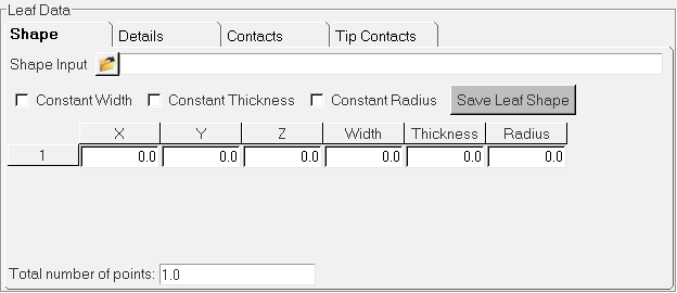
Figure 16. -
Enter the required data for Leaf 2 in the Shape tab of the Property Editor as
shown in Figure 17.
- From the Shape Input field, browse and select the Leaf_2.csv file.
- For Width, enter 64.
- For Thickness, enter 7.
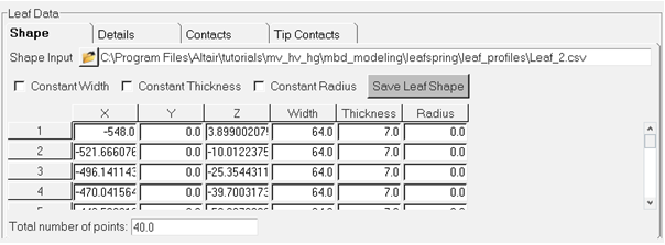
Figure 17.The Leaf 2 graphics are displayed in the Canvas section.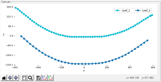
Figure 18. -
Enter the required data for Leaf 2 in the Details tab of the Property Editor as
shown in Figure 19.
- Open the Details tab.
- From the Type drop-down menu, select Graduated.
- For Front Leaf Length, enter 548.
- For Rear Leaf Length, enter 560.
- For No. of Beams in front, enter 15.
- For No. of Beams in rear, enter 15.

Figure 19. -
For the Total number of Contact points, enter 12 and
press Enter.
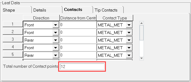
Figure 20.The Contacts table for Leaf 2 is generated based upon the values entered. -
Enter the data shown in Table 2 into the Contacts table.
Table 2. S. No Direction Distance Contact Type 1 Front 95 METAL_METAL 2 Front 155 METAL_METAL 3 Front 234 METAL_METAL 4 Front 311 METAL_METAL 5 Front 385 METAL_METAL 6 Front 457 METAL_METAL 7 Rear 105 METAL_METAL 8 Rear 155 METAL_METAL 9 Rear 234 METAL_METAL 10 Rear 311 METAL_METAL 11 Rear 385 METAL_METAL 12 Rear 457 METAL_METAL 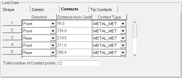
Figure 21.The entered contact points are plotted on Leaf 2 and are displayed in the Canvas section.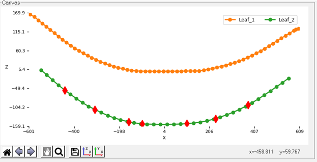
Figure 22. -
Verify the Front Tip Liner and the Rear Tip
Liner check boxes are not selected.
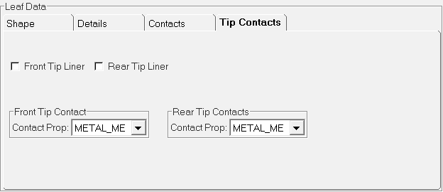
Figure 23.
Enter Leaf 3 Data
In this step, you will enter the required data for Leaf 3 using the Property Editor.
-
From the Shape Input field, browse and select
Leaf_3.csv.
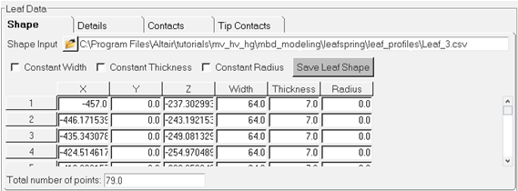
Figure 24.The Leaf 3 graphics are displayed in the Canvas section. -
Enter the required data for Leaf 3 in the Details tab of the Property Editor as
shown in Figure 25.
- Open the Details tab.
- From the Type drop-down menu, select Graduated.
- For Front Leaf Length, enter 457.
- For Rear Leaf Length, enter 463.
- For No. of Beams in front, enter 15.
- For No. of Beams in rear, enter 15.

Figure 25. -
Enter the data shown in into the Contacts table.
Table 3. S. No Direction Distance Contact Type 1 Front 95 METAL_METAL 2 Front 155 METAL_METAL 3 Front 234 METAL_METAL 4 Front 311 METAL_METAL 5 Front 385 METAL_METAL 6 Rear 105 METAL_METAL 7 Rear 155 METAL_METAL 8 Rear 234 METAL_METAL 9 Rear 311 METAL_METAL 10 Rear 385 METAL_METAL 
Figure 26.The entered contact points are plotted on Leaf 3 in the Canvas section.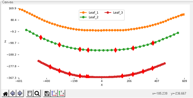
Figure 27.
Enter Leaf 4 Data
In this step, you will enter the required data for Leaf 4 using the Property Editor.
-
From the Shape Input field, browse and select the
Leaf_4.csv file.
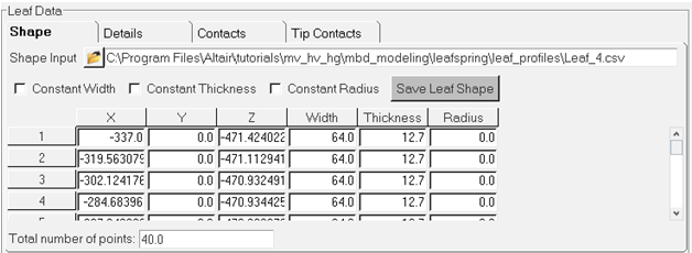
Figure 28. -
Enter the required data for Leaf 4 in the Details tab of the Property Editor as
shown in Figure 29.
- Open the Details tab.
- From the Type drop-down menu, select Graduated.
- For Front Leaf Length, enter 337.
- For Rear Leaf Length, enter 343.
- For No. of Beams in front, enter 15.
- For No. of Beams in rear, enter 15.
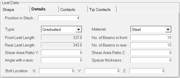
Figure 29. -
Enter the data shown in into the Contacts table.
Table 4. S. No Direction Distance Contact Type 1 Front 95 METAL_METAL 2 Front 155 METAL_METAL 3 Front 234 METAL_METAL 4 Front 311 METAL_METAL 5 Rear 105 METAL_METAL 6 Rear 155 METAL_METAL 7 Rear 234 METAL_METAL 8 Rear 311 METAL_METAL 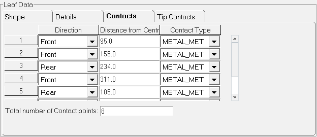
Figure 30.The entered contact points are plotted on Leaf 4 in the Canvas section.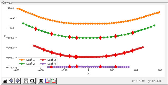
Figure 31.
Enter Leaf Ends Data
In this step, you will enter data for the Leaf Ends components using the Property Editor.
Leaf ends parameters provide the details about the eye hook types at front and at the rear ends. Three spring eye types are supported.
-
From the Leaf Spring Components browser section, click the
Front_leaf_end component.
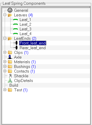
Figure 32.The Property Editor opens within the dialog. -
Enter the necessary data in the Property Editor as indicated in Figure 33.
- From the Leaf End Type drop-down menu, select Spring Eye.
- From the Tyle drop-down menu, select Berlin.
- For Inner Radius, enter 20.
- Select the Spring Eye Location checkbox.
- For X, enter -624.973.
- For Y, enter 0.
- For Z, enter 184.
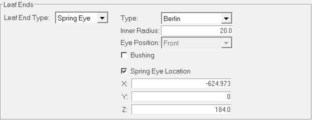
Figure 33. -
Enter the necessary data in the Property Editor.
- From the Leaf End Type drop-down menu, select Spring Eye.
- From the Tyle drop-down menu, select Berlin.
- For Inner Radius, enter 20.
- Select the Spring Eye Location checkbox.
- For X, enter 636.027.
- For Y, enter 0.
- For Z, enter 139.5.
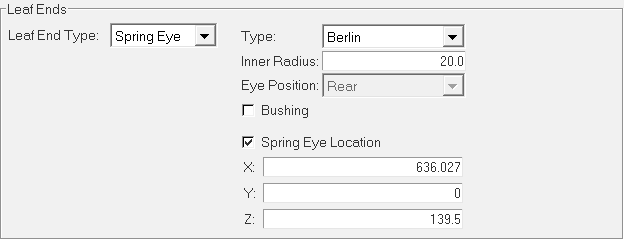
Figure 34.
Enter Clips Data
In this step, you will enter data for the Clips components using the Property Editor.
Clip parameter is used to define the Clip properties. The number of clips added in the clips parameter are reflected in the Clip Details.
-
From the Leaf Spring Components browser section, click the
Clip_1 component.
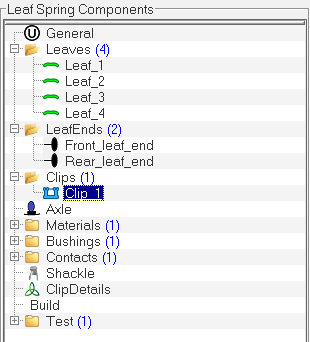
Figure 35.The Property Editor opens within the dialog. -
Enter the necessary data in the Property Editor as indicated in Figure 36.
- From the Type drop-down menu, select Pin Clip.
- For Height, enter 24.
- For Width, enter 64.
- For Pin Diameter, enter 3.75.
- For Depth, enter 3.75.
- From the Contact Property drop-down menu, select METAL_METAL.
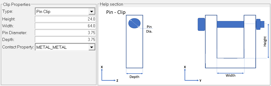
Figure 36. -
Enter the necessary data in the Property Editor as indicated below.
- From the Type drop-down menu, select UnderSlung.
- For Front Inactive Length, enter 76.196.
- For Rear Inactive Length, enter 76.196.
- For Load on LeafPack, enter 3000.
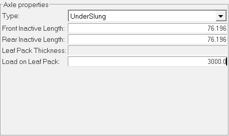
Figure 37.
Enter Material Data
In this step, you will enter data for the Materials component using the Property Editor.
-
Enter the necessary data in the Property Editor as indicated in Figure 38.
- For Young's Modulus, enter 205000.
- For Shear Modulus, enter 80000.
- For Density, enter 7.8e-06.
- For Beam Damping Ratio, enter 0.001.
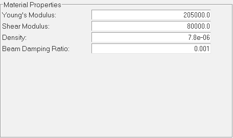
Figure 38.
Define Bushing Properties
In this step, you will define the Bushings component properties using the Property Editor.
-
Use the default values for the component.
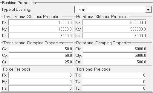
Figure 39.
Enter Contacts Data
In this step, you will add a Contacts component contact and enter data for the components using the Property Editor.
-
Enter the necessary data for METAL_METAL using the Property Editor as shown in
Figure 40.
- For Clearance(x1), enter 0.
- For Stiffness(k), enter 100000.
- For Exponent(e), enter 2.1.
- For Max. Damping(c), enter 50.
- For Max. Penetration depth(d), enter 0.05.
- Verify the Friction check box is not selected.
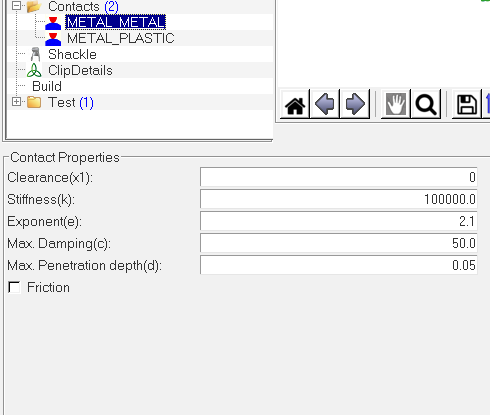
Figure 40. -
Enter the necessary data for METAL_PLASTIC using the Property Editor as shown
in Figure 41.
- For Clearance(x1), enter 2.42.
- For Stiffness(k), enter 600.
- For Exponent(e), enter 2.1.
- For Max. Damping(c), enter 1.
- For Max. Penetration depth(d), enter 0.005.
- Verify the Friction check box is not selected.
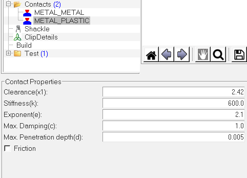
Figure 41. -
Update the Contact Property for the Clip_1 contact as shown in Figure 42.
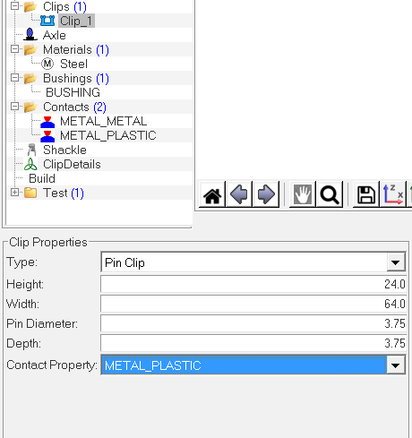
Figure 42.
Enter Shackle Data
In this step, you will enter data for the Shackle component using the Property Editor.
-
Enter the necessary data for the component in the Property Editor as shown in
Figure 43.
- From the Location drop-down menu, select Rear.
- For Mass, enter 1.
- For Thickness, enter 15.
- For Length(Lss), enter 88.768.
- For Shackle Center Offset, enter 20.
- Verify the Bushing check box is not selected.
- From the Type drop-down menu, select Compression.
- For Inertia IXX, enter 500.
- For Inertia IYY, enter 500.
- For Inertia IZZ, enter 500.
- For Mounting Len(Lcc), enter 1284.883.
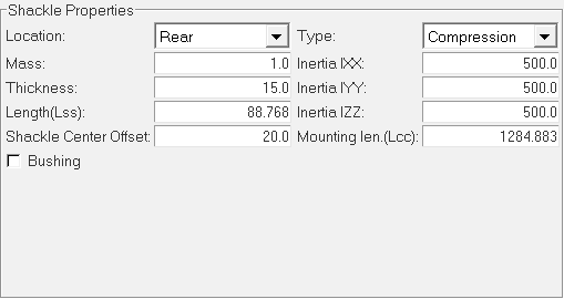
Figure 43.
Enter Clip Details
In this step, you will enter data for the clip using the ClipDetails section of the Property Editor.
-
Enter the necessary data for the Clip 1 component as shown in Figure 44.
- From the Direction drop-down menu, select Front.
- For Distance, enter 450.
- From the Clip drop-down menu, select Clip_1.
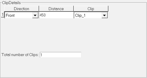
Figure 44.
Import the Model
In this step, you will import the leaf spring model into MotionView.
The Leaf Spring Builder saves the data in an .lpf file. The file can be saved and loaded in the Leaf Spring Builder interface. The file is readable and is in TiemOrbit format. To make model changes, edit the spring data in the interface and build a new leaf spring system definition.
-
Click Build.
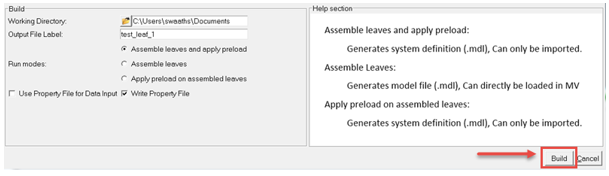
Figure 45.The Leaf Builder Message dialog opens.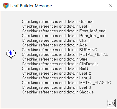
Figure 46.Note: The Leaf Builder Message dialog shows the model checks that are performed before the test job is submitted to the MotionSolve. -
Click OK to exit the
dialog.
MotionSolve is invoked in the background and it displays several windows as it runs, in order to generate the leaf spring MDL system definition file.
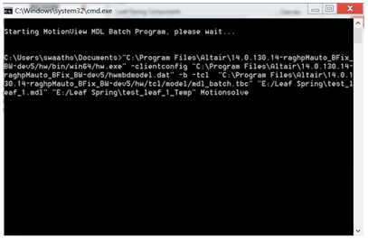
Figure 47. -
Once the MotionSolve process is done, Close the
Leaf Builder dialog.
The Leaf Builder Message window is displayed.
Figure 48. -
From the Project Browser, click
Model.
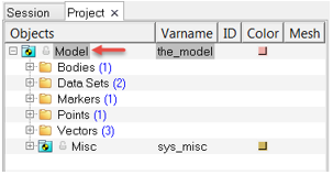
Figure 49. -
In the panel area, expand the Import/Export tab.
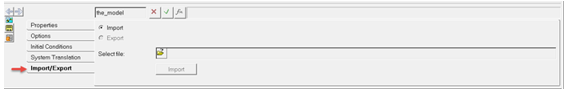
Figure 50. -
Click Import.
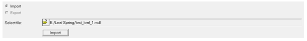
Figure 51.The Import Definition dialog opens. -
Click OK to accept the
default options.
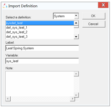
Figure 52. -
From the Project Browser, click the Leaf Spring
System and resolve the attachments.
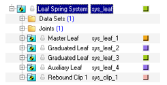
Figure 53.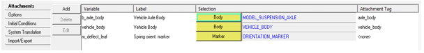
Figure 54.The Leaf Spring is displayed in the MotionView graphics window.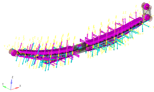
Figure 55.
Test the Model
In this step, you will test the leaf spring model using the Leaf Spring Builder.
-
From the Leaf Spring Components section, click the Test
component.
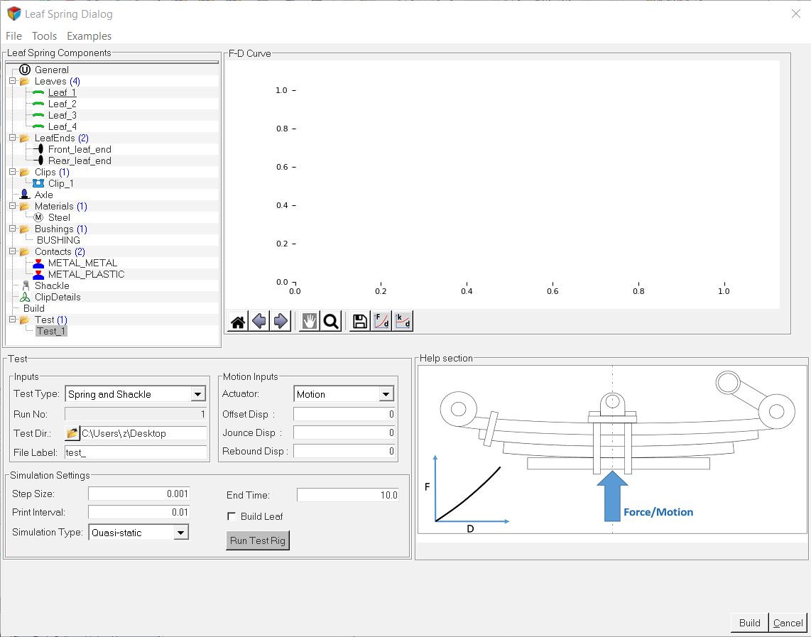
Figure 56. -
Browse and locate the Testing Directory and enter the data as indicated in
Figure 57.
- For Test Rig Type, select Force.
- For the Simulation Type, select Quasi-static analysis.
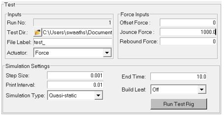 Figure 57.
 -
Click the Run Test Rig button.
The Leaf Builder Message window opens.
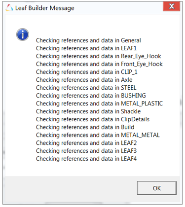
Figure 58.Note: The message window shows the model checks that are performed before the test job is submitted to MotionSolve. -
Click OK to exit the window.
MotionSolve is invoked in the background and displays several windows as it runs.
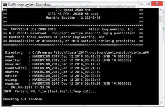 Figure 59. Once the run process is completed, the F-D Curve shown in Figure 60 is generated in the Leaf Builder.
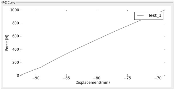 Figure 60.