HM-3430: Part Replacement Through Connectors
A new part is needed in the assembly. In this tutorial you will learn how to delete the original component, import a new part, and update the connections. You will also export the connector information to a single file, and then export the entire FE input deck and observe how the connector information is preserved.
- Replace the rear truss component, Rear_Truss_1, with a new, similar part and then update the affected connectors.
- Export the connector information
- export the FE deck and view the connector information in the deck
After the modeling of the assembly is complete, a design change might be made to any one of the parts. When this occurs, you must replace the current part(s) in the model with the new, similar one(s) and update the affected connections (welds).
This exercise uses the frame_assembly_3.hm file, which can be found in the hm.zip file. Copy the file(s) from this directory to your working directory.
Open the Model File
In this step you will open and view the model file.
-
Open a model file by clicking from the menu bar, or by clicking
 on
the Standard toolbar.
on
the Standard toolbar.
Load the Connector Browser
In this step you will load the Connector Browser.
-
Review the layout of the Connector Browser. Currently there
are no components or connectors listed because there are no connectors in the
model.
Note: You can use the Connector Browser to view and manage the connectors in your model. The top portion of the browser is referred to as the Link Entity Browser, and it displays information about the linked entities in your model. The middle portion is referred to as the Connector Entity Browser, and it contains a list of the connectors in your model. The bottom portion of the browser is referred to as the Connector Entity Editor, and it displays attributes assigned to the connector(s) selected in the Connector Entity Browser. HyperMesh groups the connectors based on their connection type.
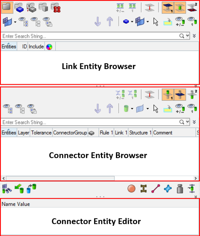
Figure 1.
Import Component to Set Up Link Update
In this step you will import rear_truss_1_new.hm to set up the link update.
-
In the Model Browser, Component folder, right-click on
Rear_Truss_1 and select Isolate from the context menu.
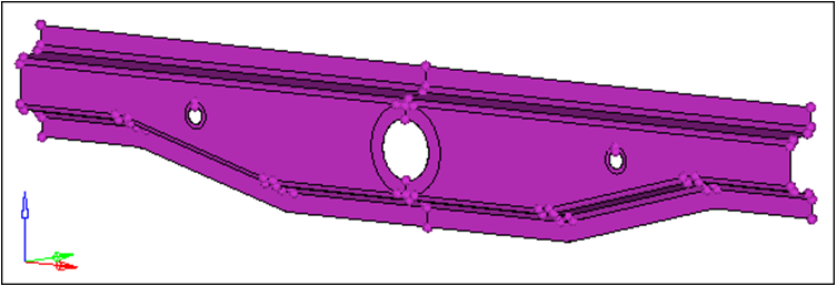
Figure 2. -
Under File selection, click
 .
.
-
Click Import.
HyperMesh imports rear_truss_1_new on top of rear_truss_1.

Figure 3.
Update Connector Links
In this step you will use the Connector Browser to update the connector links to the new component.
-
In the Update window, click the Link Select field in the
Search column.
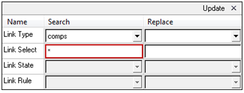
Figure 4. -
Click proceed.
HyperMesh inserts Rear_Truss_1 into the Link Select field.
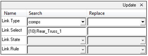
Figure 5. -
Click proceed.
HyperMesh inserts Rear_Truss_1.1 in the Link Select field.
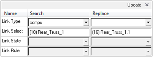
Figure 6.
Realize the Connectors
In this step you will realize the connectors in the component Con_Rear_Truss.
Save Connector Information
In this step you will save the connector information to an XML file.
-
At the bottom of the Connector Browser, click
 (Export connectors -XML).
- In the Export to file dialog, navigate to the location where you would like to save the XML file and click Save.
- In a text editor, open the XML file.
- Inspect the file and observe how the connector information has been saved. In the future, you can use the XML file to import connectors.