HM-3410: Create Area Connectors
Area connectors must be meshed in order to work properly. When the connector’s location is existing FE mesh elems, the connector automatically gets meshed to match the elements chosen. However, after creating an area connector on surfs, lines, or along nodes, you must use the automesh options (which display when you select one of these locations types) to create a mesh on the connector area.
- Create and realize area connectors in a single process
- Create, but not realize, area connectors
- Create FE representations of previously-created area connectors
This exercise uses the frame_assembly_1.hm file, which can be found in the hm.zip file. Copy the file from this directory to your working directory.
Open the Model File
In this step you will open and view the model file.
-
Open a model file by clicking from the menu bar, or clicking
 on
the Standard toolbar.
on
the Standard toolbar.
Load the Connector Browser
In this step you will load the Connector Browser.
-
Review the layout of the Connector Browser. Currently there
are no components or connectors listed because there are no connectors in the
model.
Note: You can use the Connector Browser to view and manage the connectors in your model. The top portion of the browser is referred to as the Link Entity Browser, and it displays information about the linked entities in your model. The middle portion is referred to as the Connector Entity Browser, and it contains a list of the connectors in your model. The bottom portion of the browser is referred to as the Connector Entity Editor, and it displays attributes assigned to the connector(s) selected in the Connector Entity Browser. HyperMesh groups the connectors based on their connection type.
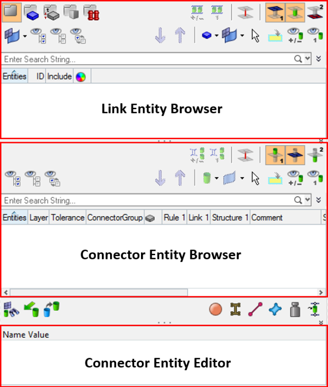
Figure 1.
Create an Adhesive Connection on the Top Flange
In this step you will create an adhesive connection between component Left_Rail_1 and Left_Rail_2 on the top flange.
-
Select one element on the top flange of the Left_Rail_1 component as indicated
in the following image.
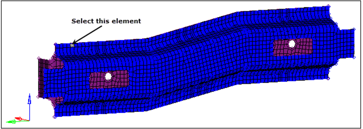
Figure 2. -
Click elems >> by face.
The entire flange is selected.
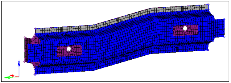
Figure 3. -
Select the components, Left_Rail_1 and
Left_Rail_2.
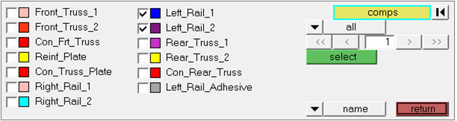
Figure 4. -
Set the hexa thickness to shell gap.
Note: This option projects directly to the shell component and takes no account of the thickness of the shell components.
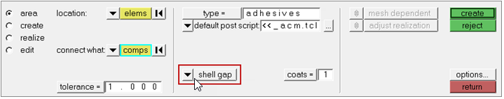
Figure 5. -
In the Connector Entity Browser, right-click on the unrealized adhesive
connector and select Rerealize from the context menu.
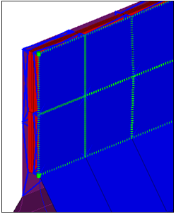
Figure 6.
Create an Adhesive Connection on the Bottom Flange
In this step you will create an adhesive connection between component Left_Rail_1 and Left_Rail_2 on the bottom flange.
-
Select the row of nodes on the outer flange of the Left_Rail_1 component by
first selecting the left most node on the bottom flange of Left_Rail_1 and then
selecting the right-most node on the bottom flange as indicated in the following
image.
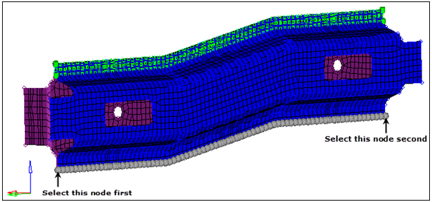
Figure 7. -
In the element size= field, type 3.
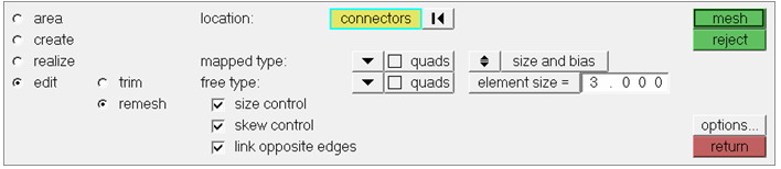
Figure 8. -
Inspect the new adhesive created.
Note: When creating area connectors from elements, HyperMesh automatically meshes the area connector using the current mesh. If the area connector is created from nodes, lines, or surfaces and the default mesh is unsuitable from the area subpanel, then you can apply a manual mesh.
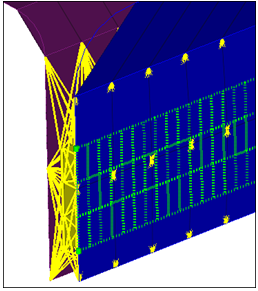
Figure 9.