HM-2025: Auto-Midsurface with Advanced Extraction
In this tutorial you will use auto-midsurfacing with advanced extraction options.
- Use the offset+planes+sweeps option when midsurfacing
- Manually correct gaps in an auto-generated midsurface using the plates edit function
In this tutorial, you will be using CAD geometry data for a box with thin ribs inside of it. Because the geometry consists of thin planar sections, it is assumed that it will be modeled for FEA as shell elements. The elements will be created on the mid-planes of each section.
This exercise uses the Insert_planes.hm file, which can be found in the hm.zip file. Copy the file from this directory to your working directory.
Open the Model File
In this step you will open and view the model file.
-
In the Open Model dialog, open the
Insert_planes.hm model file.
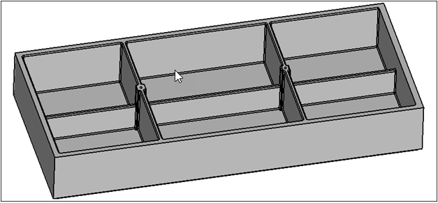
Figure 1. -
In the Auto Midsurface panel, click the toggle and select closed
solid.
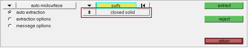
Figure 2. -
From the drop-down menu, select offset+planes+sweeps.
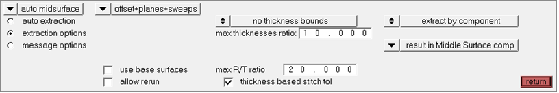
Figure 3. -
Shade the model's geometry and surface edges by clicking
 on
the Visualization toolbar.
on
the Visualization toolbar.
-
Review the generated midsurface by hiding the Body.1 component in the Model Browser.
Some of the plates do not properly cross.
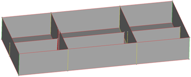
Figure 4.
Resolve Midsurface Gaps
In this step you will use the edit plates subpanel to resolve midsurface gaps.
-
On the Visualization toolbar, set the geometry display mode to
 .
.
-
From the panel area, select the interim edit tools from
the drop-down.
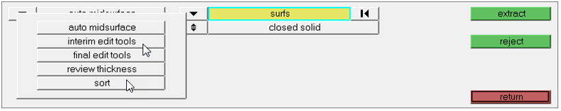
Figure 5. -
From the edit plates subpanel, click show/edit
all.
HyperMesh populates the Model Browser with plates that were detected by the tool.Note: If you have not yet extracted the middle surface using either the offset+planes or offset+planes+sweeps options, then the model will not have any plate information yet. Plate components will not be populated in this situation.
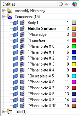
Figure 6. -
Select any face from the long interior rib, as shown in the following image.
This rib was split into three groups by the algorithm and needs to be reunited
into one component.
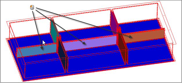
Figure 7. -
Select the two remaining plates from the long interior rib.
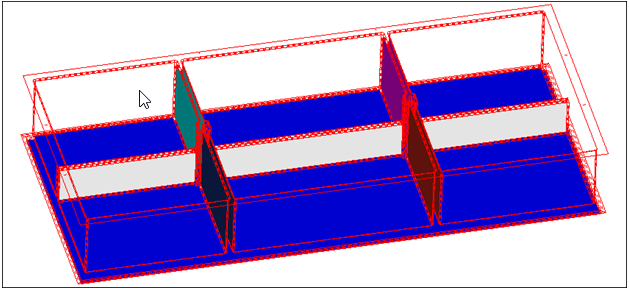
Figure 8. -
Merge the three plates into a single planar plate by setting the plate type to
planar.
Figure 9. -
Using the full plate selector, select the newly created plate.
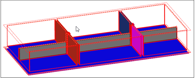
Figure 10. -
Click the single surface selector.
The selected plate is isolated, and one side is colored blue while the other side is colored green.
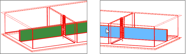
Figure 11. -
Notice the long narrow surface that displays with the left-most plate. Select
it with the single plate selector and set it to plate edge.
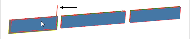
Figure 12. -
Review the generated midsurface by hiding the Body.1 component in the Model Browser. The plates are closer together but they are still
not the full length of the rib due to the holes that trim the plates.
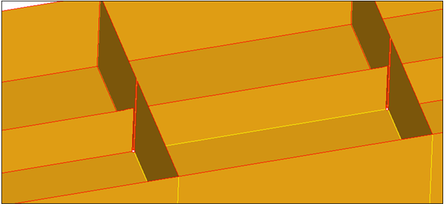
Figure 13.
Use Plates Edit
In this step you will use plates edit to resolve remaining gaps.
In this step you will need to tell the auto-midsurface algorithm not to trim the plates where the holes are located.
-
In the interim edit tools panel, edit plates subpanel, click
show/edit all.
HyperMesh populates less plate components in the Model Browser because some plates were merged in the previous steps.
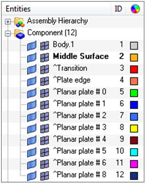
Figure 14. -
Using the single surface surfs selector, select all four internal surfaces of
the two holes.
Note: Each hole has two internal surfaces.
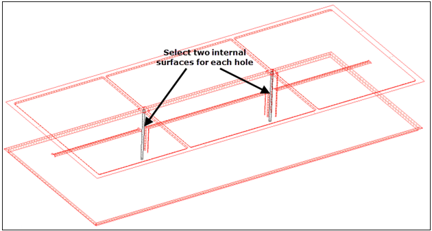
Figure 15. -
Click not a trim surface.
HyperMesh organizes the selected surfaces into a new component labeled ^Not a trim surface.
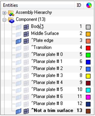
Figure 16. -
Review the generated midsurface by hiding the Body.1 component in the Model Browser. There is now a yellow edge where the plates meet,
which indicates that the plates are intersected correctly. It would have been
possible to reorganize the plates and create the Not a trim surface component at
the same time.
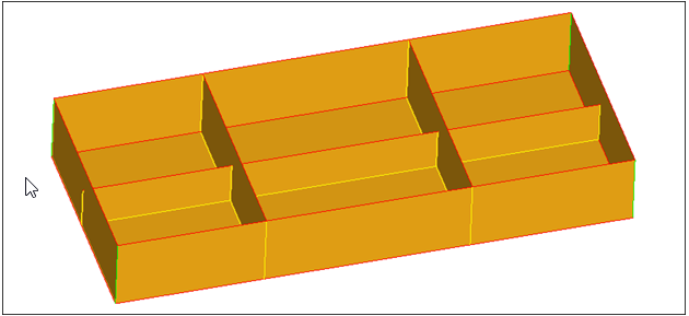
Figure 17.
Save Your Work
In this optional step you will save your work.
This step is optional.
The model now contains surfaces on the mid-plane of the part. You used insert planes and plates edit to ensure that there were no erroneous gaps in the generated midsurfaces. You can now mesh these surfaces, or further modify their topology, depending on the requirements of the analysis.