HM-2010: Import and Repair CAD
In this tutorial you will learn how to import and repair CAD.
- Delete untrimmed surfaces
- Close missing surfaces
- Set the cleanup tolerance
- Equivalence free edges
- Delete duplicate surfaces
- Correcting any errors in the geometry from import
- Creating the simplified part needed for the analysis
- Meshing a part all at once
- Ensuring proper connectivity of mesh
- Obtaining a desirable mesh pattern and quality
This exercise uses the clip_repair.hm file, which can be found in the hm.zip file. Copy the file from this directory to your working directory.
Open the Model File
In this step you will open and view the model file.
- Start HyperMesh Desktop.
- From the menu bar, click .
- In the Open Model dialog, open the clip_repair.hm model file.
View the Model
In this step you will view the model to evaluate its integrity.
-
To open the Auto Geometry Cleanup panel, click from the menu bar.
The surface edges are now colored according to their topology status. This occurs because Geometry Color is set to
 .
. -
To display the model's geometry in wire frame mode, click
 on the Visualization toolbar.
Note: The Visualization toolbar contains icons that control the display of the surfaces and surface edges. Surfaces can be shaded with or without edges or wireframe. Right-click the icons to access the drop-down menu for additional options. Place your mouse over the cursor to view a description of the button’s functionality.
on the Visualization toolbar.
Note: The Visualization toolbar contains icons that control the display of the surfaces and surface edges. Surfaces can be shaded with or without edges or wireframe. Right-click the icons to access the drop-down menu for additional options. Place your mouse over the cursor to view a description of the button’s functionality. -
To open the Visualization Browser and access the Topology options, click
 .
Note: The Topology options control the display of the surfaces and surface edges. Surfaces can be shaded or wireframe. The check boxes within the Visualization Browser turn the display of the different edge types and fixed points (surface vertices) on or off.
.
Note: The Topology options control the display of the surfaces and surface edges. Surfaces can be shaded or wireframe. The check boxes within the Visualization Browser turn the display of the different edge types and fixed points (surface vertices) on or off. -
Observe the locations where there are closed loops of free edges. These are
locations that probably have missing surfaces.
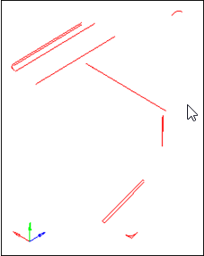
Figure 1. -
To shade the model's geometry and surface edges, click
 on
the Visualization toolbar.
on
the Visualization toolbar.
-
Note the areas to be worked on:
- A surface that overhangs a round corner
- A missing surface
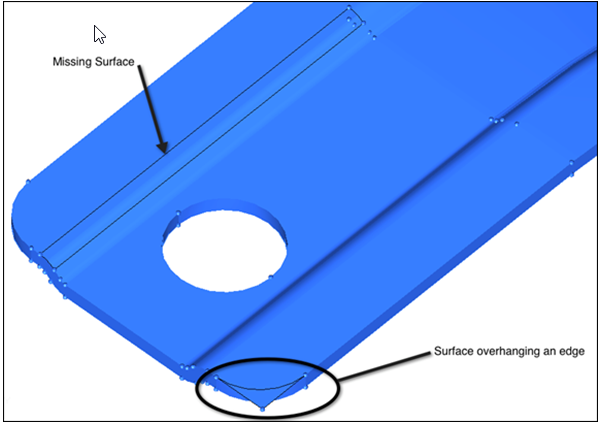
Figure 2.
Delete a Surface
In this step you will delete the surface that overhangs the round corner.
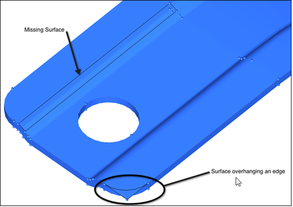
Figure 3.
Create Surfaces to Fill Gaps
In this step you will create surfaces to fill large gaps in the model.
-
Zoom into the area indicated in the following image.
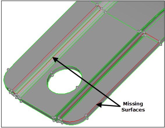
Figure 4.
Set Global Geometry Cleanup Tolerance
In this step you will set the global geometry cleanup tolerance to .01.
- Press O to open the Options panel.
- Go to the geometry subpanel.
- In the cleanup tol = field, type 0.01 to stitch the surfaces with a gap less than 0.01.
- To exit the panel, click return.
Combine Multiple Free Edge Pairs
In this step you will combine multiple free edge pairs at one time with the equivalence tool.
Combine Free Edge Pairs Using the Toggle
In this step you will combine free edge pairs, one pair at a time, using the toggle.
-
Click one of the free edges shown in the following image. When you select the
edge, it will change from red to green, indicating that the free edge pair has
been equivalenced.
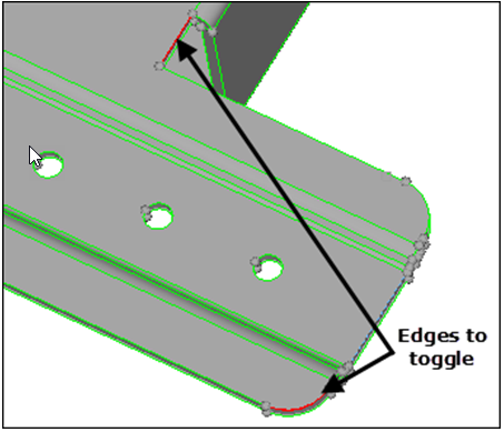
Figure 5.
Combine Free Edge Pairs Using Replace
In this step you will combine the remaining free edge pairs using replace.
-
In the Model Browser, View folder, right-click on
View2 and select Show from the
context menu.
The graphics area displays two edges to retain and remove for replacement.
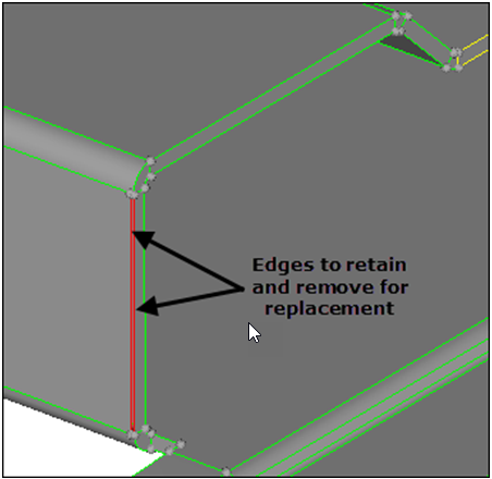
Figure 6. -
To close the gap, click Yes.
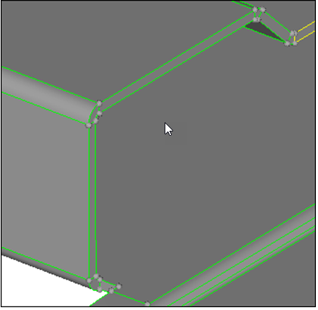
Figure 7.
Find Duplicate Surfaces
In this step you will find and delete all duplicate surfaces.
Observe Free Edges or Duplicate Surfaces
In this step you will observe the model to identify any remaining free edges, or missing or duplicate surfaces.
-
On the Visualization toolbar, change the geometry color mode to
 and click to
shade the model's geometry and surface edges.
and click to
shade the model's geometry and surface edges.
Save Your Work
In this optional step you will save your work.
With the cleanup operations completed, now is a good time to save your work. This step is optional.