Surface Meshing Mesh Controls
Model, local, refinement, and feature mesh controls for surface meshing.
- Feature mesh controls are applied first.
- Model and local mesh controls are applied second, in the following order,
according to their configuration. If any mesh controls have the same
configuration, meshing is applied starting from the smallest size up to the
largest:
- Rigid body (surface-based only)
- QI optimize
- Size and bias
- Edge deviation
- Surface deviation (surface-based)/Adaptive (element-based)
Model and Local
Model and local mesh controls define the meshing mode, element size, element type, and additional parameters used to create a mesh of shell elements using surface geometry or existing shell elements.
Size and Bias
- Main Parameters
-
Table 1. Parameters Parameter Description Use Model Settings Set all of the main parameters from the model control. For local controls only.
Element Size Average element size. The length of any active (shared or free) surface edge divided by the element size determines the number of elements to place along that edge. Element Type Type of elements used to create mesh during automatic meshing. For more information, see Mesh Types.
Element Order - First
- Create elements using a linear shape function.
- Second
- Create elements using a polynomial shape function.
- Advanced Parameters
-
Table 2. Parameters Parameter Description Organization Destination Component - Original
- Store newly created elements in the component to which the surface belongs.
- Current
- Store newly created elements in the "current" active component.
Mesh Connectivity Determines how newly created elements and any adjacent existing elements are connected. - Keep
- Use existing nodes on any shared boundary edges.
- Redo
- Re-seed existing nodes along the boundary of the newly created mesh to optimize mesh quality.
- Break
- Ignore existing adjacent elements and generates mesh according to the element size and type you specified.
Valid only for model controls.
Flow Align Produces a more orthogonal quad-dominant mesh. Only available when the Element Type is set to Mixed.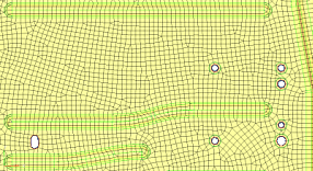
Figure 1. Flow Alignment Off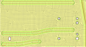
Figure 2. Flow Alignment On. Notice a straighter row of elements is produced.Size Enforces the global mesh element size with minimal min/max element size variations. Only available when Element Type is set to Mixed and Flow: Align is enabled.
Mapping Size Keeps elements roughly the same size. Skew Prevents mesh from producing highly-skewed elements. Other - Surface Based Automeshing Only Link Opposite Edges Links mesh settings on opposing edges of rectangular surfaces. Changes applied to one linked edge will be applied to the other. By default, the maximum aspect ratio (AR) to allow between large and small edge sizes of linked edges is 2.11. Manually specify an aspect ratio by setting Aspect Ratio Less Than to User Specified. Increasing the value adds more surfaces to the linked chain, whereas decreasing the value removes some surfaces from the linked chain.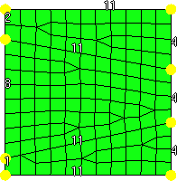
Figure 3. Link Opposite Edges Selected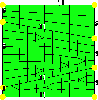
Figure 4. Link Opposite Edges Selected and Aspect Ratio Less Than = Auto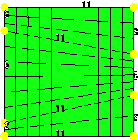
Figure 5. Link Opposite Edges Selected, Aspect Ratio Less Than = 8.0 - Features - Element Based Automeshing Only Parameters
-
Table 3. Parameters Parameter Description Auto Features Defines logical faces when using existing finite elements as a basis for automeshing. - Connected
- Detect features based on the specified feature angle, and make additional effort to void any "orphan" or non-closed feature lines.
- Auto Detect
- Detect features based on the specified feature angle.
- Surface Edges
- Automatically detect and utilize geometric
lines associated with selected elements as
features in the re-meshing operation.
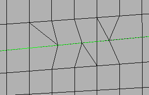
Figure 6. Before Re-Meshing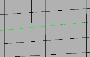
Figure 7. After Re-Meshing, Surface Edges Selected - None
- Ignore extra features defined by any of the above methods.
User Features A selection of user-created 1D elements which define features that need to be captured along with any feature angle-based features. Only 1D elements should be selected here, as any other element selections are ignored. Anchor Nodes Nodes that will remain and be re-used in the new mesh. Anchor nodes are "fixed" so that the automesher cannot move or replace them; in essence, they are exceptions to the re-meshing operation, and the new mesh must utilize them.
QI Optimize
- Main Parameters
-
Table 4. Parameters Parameter Description Use Model Settings Set all of the main parameters from the model control. For local controls only.
Element Size Average element size. The length of any active (shared or free) surface edge divided by the element size determines the number of elements to place along that edge. Element Type Type of elements used to create mesh during automatic meshing. For more information, see Mesh Types.
Element Order - First
- Create elements using a linear shape function.
- Second
- Create elements using a polynomial shape function.
Criteria File Specify a criteria file that will be used to automatically generate criteria. - Advanced Parameters
-
Table 5. Parameters Parameter Description Organization Destination Component - Original
- Store newly created elements in the component to which the surface belongs.
- Current
- Store newly created elements in the "current" active component.
Mesh Connectivity Determines how newly created elements and any adjacent existing elements are connected. - Keep
- Use existing nodes on any shared boundary edges.
- Redo
- Re-seed existing nodes along the boundary of the newly created mesh to optimize mesh quality.
- Break
- Ignore existing adjacent elements and generates mesh according to the element size and type you specified.
Valid only for model controls.
Flow Align Produces a more orthogonal quad-dominant mesh. Only available when the Element Type is set to Mixed.
Figure 8. Flow Alignment Off
Figure 9. Flow Alignment On. Notice a straighter row of elements is produced.Size Enforces the global mesh element size with minimal min/max element size variations. Only available when Element Type is set to Mixed and Flow: Align is enabled.
Mapping Size Keeps elements roughly the same size. Skew Prevents mesh from producing highly-skewed elements. Other - Surface Based Automeshing Only Smooth Across Common Edges Node smoothing moves nodes across adjacent surface edges whose feature angle is less than the value specified. When selected, strict adherence to the geometry of the surface edges in not enforced for non-feature edges; some deviation from the geometry can occur. - Features - Element Based Automeshing Only
-
Table 6. Parameters Parameter Description Auto Features Defines logical faces when using existing finite elements as a basis for automeshing. - Connected
- Detect features based on the specified feature angle, and make additional effort to void any "orphan" or non-closed feature lines.
- Auto Detect
- Detect features based on the specified feature angle.
- Surface Edges
- Automatically detect and utilize geometric
lines associated with selected elements as
features in the re-meshing operation.
Figure 10. Before Re-Meshing
Figure 11. After Re-Meshing, Surface Edges Selected - None
- Ignore extra features defined by any of the above methods.
User Features A selection of user-created 1D elements which define features that need to be captured along with any feature angle-based features. Only 1D elements should be selected here, as any other element selections are ignored. Anchor Nodes Nodes that will remain and be re-used in the new mesh. Anchor nodes are "fixed" so that the automesher cannot move or replace them; in essence, they are exceptions to the re-meshing operation, and the new mesh must utilize them.
Edge Deviation
- Main Parameters
-
Table 7. Parameters Parameter Description Use Model Settings Set all of the main parameters from the model control. For local controls only.
Minimum Size Minimum allowable element size. Maximum Size Maximum allowable element size. Maximum Deviation Allowable deviation between the element edge and the surface edge. To meet this requirement, element edge lengths along a curved surface edge are reduced as needed down to a lower limit set by the minimum element size. Maximum Feature Angle Maximum angle across which elements can be maintained. When two adjacent elements’ normals exceed this angle, a new set of nodes is created between them to maintain clean feature lines. Using higher value results in elements spanning the feature line. 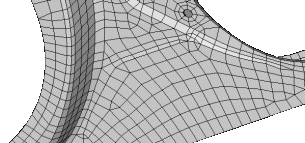
Figure 12. . With an appropriate value, the features lines are preserved.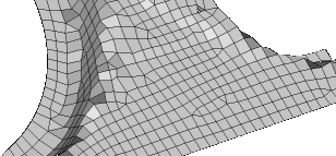
Figure 13. . If the feature angle is too high, the feature lines are blurred.Element Type Type of elements used to create mesh during automatic meshing. For more information, see Mesh Types.
Element Order - First
- Create elements using a linear shape function.
- Second
- Create elements using a polynomial shape function.
- Advanced Parameters
-
Table 8. Parameters Parameter Description Organization Destination Component - Original
- Store newly created elements in the component to which the surface belongs.
- Current
- Store newly created elements in the "current" active component.
Mesh Connectivity Determines how newly created elements and any adjacent existing elements are connected. - Keep
- Use existing nodes on any shared boundary edges.
- Redo
- Re-seed existing nodes along the boundary of the newly created mesh to optimize mesh quality.
- Break
- Ignore existing adjacent elements and generates mesh according to the element size and type you specified.
Valid only for model controls.
Flow Align Produces a more orthogonal quad-dominant mesh. Only available when the Element Type is set to Mixed.
Figure 14. Flow Alignment Off
Figure 15. Flow Alignment On. Notice a straighter row of elements is produced.Mapping Size Keeps elements roughly the same size. Skew Prevents mesh from producing highly-skewed elements. Other - Surface Based Automeshing Only Link Opposite Edges Links mesh settings on opposing edges of rectangular surfaces. Changes applied to one linked edge will be applied to the other. By default, the maximum aspect ratio (AR) to allow between large and small edge sizes of linked edges is 2.11. Manually specify an aspect ratio by setting Aspect Ratio Less Than to User Specified. Increasing the value adds more surfaces to the linked chain, whereas decreasing the value removes some surfaces from the linked chain.
Figure 16. Link Opposite Edges Selected
Figure 17. Link Opposite Edges Selected and Aspect Ratio Less Than = Auto
Figure 18. Link Opposite Edges Selected, Aspect Ratio Less Than = 8.0 - Features - Element Based Automeshing Only
-
Table 9. Parameters Parameter Description Auto Features Defines logical faces when using existing finite elements as a basis for automeshing. - Connected
- Detect features based on the specified feature angle, and make additional effort to void any "orphan" or non-closed feature lines.
-
Figure 19. Refore Re-Meshing
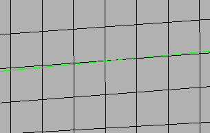 Figure 20. After Re-Meshing, with Connected
Features
Figure 20. After Re-Meshing, with Connected
Features - Auto Detect
- Detect features based on the specified feature angle.
- Surface Edges
- Automatically detect and utilize geometric
lines associated with selected elements as
features in the re-meshing operation.
Figure 21. Before Re-Meshing
Figure 22. After Re-Meshing, with Surface Edges Selected - None
- Ignore extra features defined by any of the above methods.
User Features A selection of user-created 1D elements which define features that need to be captured along with any feature angle-based features. Only 1D elements should be selected here, as any other element selections are ignored. Anchor Nodes Nodes that will remain and be re-used in the new mesh. Anchor nodes are "fixed" so that the automesher cannot move or replace them; in essence, they are exceptions to the re-meshing operation, and the new mesh must utilize them.
Surface Deviation
- Main Parameters
-
Table 10. Parameters Parameter Description Use Model Settings Set all of the main parameters from the model control. For local controls only.
Minimum Size Minimum allowable element size. When there are model and local mesh controls for surface deviation, and the minimum size of neighboring mesh controls are different, the minimum size will automatically propagate from the smaller mesh size to neighboring surfaces.
Maximum Size Maximum allowable element size. Growth Rate Determines how rapidly elements can increase in size as they are created further and further away from features. 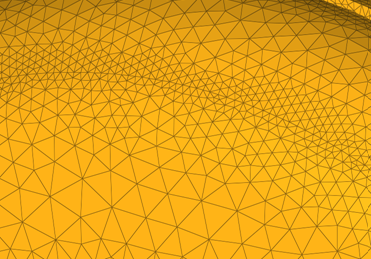
Figure 23. Growth Rate. Elements further from the features grow larger with each row.Span Angle Controls the element size at curve input. The smaller the angle, the more refined curvature will be and the more preserved the input shape will be. By default span angle is 25.0 degrees. Valid only for element-based controls
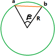
Figure 24. Span Angle. β is the span angle of the edge ab. The length of ab is less than 2R( sin β/2 ).Feature Angle Determines which features to preserve. The mesher identifies features internally and preserves/refine them based on the defined feature angle.
Valid only for element-based controls.
Element Order - First
- Create elements using a linear shape function.
- Second
- Create elements using a polynomial shape function.
- Advanced Parameters
-
Table 11. Parameters Parameter Description Organization Mesh Connectivity Determines how newly created elements and any adjacent existing elements are connected. - Keep
- Use existing nodes on any shared boundary edges.
- Redo
- Re-seed existing nodes along the boundary of the newly created mesh to optimize mesh quality.
- Break
- Ignore existing adjacent elements and generates mesh according to the element size and type you specified.
- Features - Element Based Automeshing Only
-
Table 12. Parameters Parameter Description Auto Features Defines logical faces when using existing finite elements as a basis for automeshing. - Connected
- Detect features based on the specified feature angle, and make additional effort to void any "orphan" or non-closed feature lines.
-
Figure 25. Refore Re-Meshing
Figure 26. After Re-Meshing, with Connected Features - Auto Detect
- Detect features based on the specified feature angle.
- Surface Edges
- Automatically detect and utilize geometric
lines associated with selected elements as
features in the re-meshing operation.
Figure 27. Before Re-Meshing
Figure 28. After Re-Meshing, with Surface Edges Selected - None
- Ignore extra features defined by any of the above methods.
User Features A selection of user-created 1D elements which define features that need to be captured along with any feature angle-based features. Only 1D elements should be selected here, as any other element selections are ignored. Refine Features Apart from capturing the features if refine feature is turned enabled, you can define the mesh size to be applied to features selected/found by any of the above methods.
Rigid Body Mesh
- Main Parameters
-
Table 13. Parameters Parameter Description Use Model Settings Set all of the main parameters from the model control. For local controls only.
Minimum Size Minimum allowable element size. Maximum Size Maximum allowable element size. Maximum Deviation Allowable deviation between the element edge and the surface edge. To meet this requirement, element edge lengths along a curved surface edge are reduced as needed down to a lower limit set by the minimum element size. Maximum Feature Angle Maximum angle across which elements can be maintained. When two adjacent elements’ normals exceed this angle, a new set of nodes is created between them to maintain clean feature lines. Using higher value results in elements spanning the feature line.
Figure 29. . With an appropriate value, the features lines are preserved.
Figure 30. . If the feature angle is too high, the feature lines are blurred.Element Type Type of elements used to create mesh during automatic meshing. For more information, see Mesh Types.
Element Order - First
- Create elements using a linear shape function.
- Second
- Create elements using a polynomial shape function.
- Advanced Parameters
-
Table 14. Parameters Parameter Description Organization Destination Component - Original
- Store newly created elements in the component to which the surface belongs.
- Current
- Store newly created elements in the "current" active component.
Refinement
Refinement controls allow the definition of element refinement based on geometry, proximity and angle.
This is supported only for surface deviation meshing.
Geometric
| Parameter | Description |
|---|---|
| Refinement Size | Element size applied to selected entities. If the refinement size is less than the minimum size defined by the model mesh control, then the minimum size will override the refinement size. |
Proximity
| Parameter | Description |
|---|---|
| Maximum Search Angle | Defines the maximum normal angle between elements and surfaces to be considered for the proximity candidate search. |
| Maximum Proximity Distance | Performs refinement if the surfaces/elements proximity is below this value. |
| Minimum Proximity Distance | Performs refinement if the surfaces/elements proximity is above this value. |
| Proximity Within | Defines how the proximity search should be performed.
|
| Proximity Check Direction | Defines the direction in which to consider proximity.
|
| Refinement Method | Method used to refine proximity elements.
|
Angle-Based
| Parameter | Description |
|---|---|
| Direction | Defines the concave or convex angle with any direction to be
refined. Convex and concave angles are related to a polygon and
measured between surfaces/element faces. If Both is selected,
both types of angles will be refined. Figure 31. |
| Minimum Angle Limit | Minimum angle limit. The Refinement Size specified below this parameter in the Entity Editor will be assigned this angle. |
| Maximum Angle Limit | Maximum angle limit. The Refinement Size specified above this parameter in the Entity Editor will be assigned this angle. |
Feature
Feature mesh controls define the mesh density and quality of specific geometric features. These can be used to generate a high quality tria mesh on supported feature types.
- If a feature global control only exists, on-the-fly selection is prompted.
- If a feature body control only exists, it must have a pre-defined selection and on-the-fly selection is not allowed.
- If both a feature global and body control exist, the body control will always be used and the global control will be ignored.
- A surface mesh model control is required.
- The selection strictly comes from the surface mesh model control, either as a pre-defined selection or on-the-fly.
- Only the surface mesh model control selection that overlaps with any feature selection (including body or local controls) is considered.
- Feature global control will always be ignored in this case.
It is recommended that feature controls be run standalone. Combined usage with other surface mesh controls may result in a non-conformal mesh.
Global and Body
- Mesh Size Parameters
-
Table 18. Parameters Parameter Description Average Element Size The 2D element size in the model which controls the average element size. Minimum Element Size Minimum length of elements to generate in the mesh. Coarse Mesh Reduces the number of solid elements and the number of nodes. On an average, coarse mesh generates about 20 percent less nodes/elements compared to a regular volume mesher. Use Maximum Element Size Define the maximum element size instead of the average element size. Maximum element size = 1.4 * Average element size. Only available for Global mesh controls.
- Geometry Curvature Parameters
-
Table 19. Parameters Parameter Description Maximum Angle per Element The approximation of a geometry is related to the angle made by an element edge on a perfect circle. For example, if the angle is 45 degrees this will approximate a circle by 8 elements. This same measurement is extended to an arbitrary curved surface. Curvature Minimum Element Size The mesh approximates the geometry by varying the mesh size as a function of the curvature. This geometry approximation cannot result in a mesh size smaller than the Curvature minimum element size. - Mesh Quality Parameters
-
Table 20. Parameters Parameter Description Aspect Ratio Determines the quality of the mesh. The value varies from 1 (equilateral element) to infinity (flat element). The default aspect ratio value is 10. Mesh Grading The variation of the mesh in the face from the boundary to the interior is controlled by the surface mesh grading. The default value is 1.5. - Mesh Type Parameters
-
Table 21. Parameters Parameter Description Element Type Use Tria3 or Tria6 elements to create mesh. Project Mid-node Enables the projection of mid-nodes onto the faces and edges of the geometry. Mesh Pattern Determines the mesh pattern. - Auto
- Determine the faces that will be isomeshed automatically. All regular four edged faces and faces that are four sided will be isomeshed.
- Regular 4-Sided Faces
- Isomesh all regular four edged faces, even if the edges are not of similar size.
- None
- Force a free mesh on all faces in the body, even if it is a regular four edged face.
Cylinder

Figure 32. Cylinder
| Parameter | Description |
|---|---|
| Axial Mesh Size | Define the element size along the length of the selected cylindrical faces. |
| Divisions | The number of nodes along the circular direction of the cylindrical face can be controlled by specifying the number of circular mesh seeds. |
Edge
| Parameter | Description |
|---|---|
| Divisions | Edge seeds are applied by specifying the number of elements. |
Face
- Mesh Size Parameters
-
Table 24. Parameters Parameter Description Average Element Size The 2D element size in the model which controls the average element size. Minimum Element Size Minimum length of elements to generate in the mesh. - Geometry Curvature Parameters
-
Table 25. Parameters Parameter Description Maximum Angle per Element The approximation of a geometry is related to the angle made by an element edge on a perfect circle. For example, if the angle is 45 degrees this will approximate a circle by 8 elements. This same measurement is extended to an arbitrary curved surface. Curvature Minimum Element Size The mesh approximates the geometry by varying the mesh size as a function of the curvature. This geometry approximation cannot result in a mesh size smaller than the Curvature minimum element size. - Mesh Quality Parameters
-
Table 26. Parameters Parameter Description Aspect Ratio Determines the quality of the mesh. The value varies from 1 (equilateral element) to infinity (flat element). The default aspect ratio value is 10. Mesh Grading The variation of the mesh in the face from the boundary to the interior is controlled by the surface mesh grading. The default value is 1.5. Use Local Uses the local settings when enabled. The settings from the global control will be used when disabled.
Fillet

Figure 33. Fillet
- Axial Mesh Size Parameters
-
Table 27. Parameters Parameter Description Length Along Fillet Defines the element length along the length of the fillet. - Geometry Curvature Parameters
-
Table 28. Parameters Parameter Description Specification Defines the element size along the fillet curvature direction. - Number
- Enables the Number of Elements option to explicitly indicate the number of elements along the curvature direction.
- Curvature
- Enables the Maximum Angle per Element and Curvature Minimum Element Size options for defining the mesh based on these values.
- Mesh Quality Parameters
-
Table 29. Parameters Parameter Description Ignore Fillet Width Less Than Specifies the minimum fillet width to consider. Fillets with a width below this value are ignored. Aspect Ratio Determines the quality of the mesh. The value varies from 1 (equilateral element) to infinity (flat element). The default aspect ratio value is 10. Merge Small Fillets Merges adjacent small fillets before meshing in order to improve the mesh quality. Adjust Axial Length to Aspect Ratio Adjusts the length along the fillet to make sure that the aspect ratio is satisfied.
Imprint Circle
- Mesh Seeds Parameters
-
Table 30. Parameters Parameter Description Radius Calculated using radius and scale factor values. Scale Scales the user defined radius by this factor. Divisions Number of seeds along the circle. - Center Parameters
-
Table 31. Parameters Parameter Description Circle Center Defines the center of the circular edge.
Isoline
- Axial Mesh Size Parameters
-
Table 32. Parameters Parameter Description Specification Defines the given size/seed in axial and circular directions to create the mapped mesh. - Geometry Curvature Parameters
-
Table 33. Parameters Parameter Description Specification The number of nodes along the circular direction can be controlled by using maximum angle or mesh seeds. The maximum angle refers to the angle subtended by a circular spanning element edge from the axis of cylindrical face.
Merge Faces Merges selected faces to a single face. Use this parameter to avoid the creation of a thin layer of elements when meshing. - Mesh Quality Parameters
-
Table 34. Parameters Parameter Description Aspect Ratio Determines the quality of the mesh. The value varies from 1 (equilateral element) to infinity (flat element). The default aspect ratio value is 10. Curvature Minimum Element Size The mesh approximates the geometry by varying the mesh size as a function of the curvature. This geometry approximation cannot result in a mesh size smaller than the Curvature minimum element size.
Preserved Entity
Preserved Entity mesh controls define the features to preserve while meshing. Tiny features on edges or surfaces may be collapsed if the minimum element size is larger than the feature. Entities selected here will be preserved from such collapsing.
Symmetry
| Parameter | Description |
|---|---|
| Master Surface | Defines the surface to considered as the master/source for reflecting the mesh. |
| Symmetry Surface | Defines the surface to considered as the slave/target for reflecting the mesh. |
| Master Points | Defines points on the Master surface to be mapped in case there are any discontinuous edges. |
| Symmetry Points | Defines points on the Symmetry surface to be mapped in case there are any discontinuous edges. |
Washer

Figure 34. Washer
| Parameter | Description |
|---|---|
| Washer Width | Define the width of the washer around the circle. |
| Number of Layers | Defines the number of mesh layers to create around the circle. |