Connector Terminology
Overview of connector terminology.
Connector Location
The position in space at which a connector entity is created.
Entities that can be used to define the connector location depend on the connector type.
Spots
- Nodes
- Connector is created at the node location.
- Points
- Connector is created at the point location.
- Lines
- Connector is created at the center of the selected line.
- Nodelist
- The nodelist can be considered as to be a line. The treatment is the same.
Bolts
- Nodes
- Connector is created at the node location.
- Points
- Connector is created at the point location.
- Lines
- Connector is created at the center of the selected line.
Seams
- Lines, Linelist
- Connector is created at the center of the selected line.
- Nodelist
- The nodelist can be considered as to be a line. The treatment is the same.
Areas
- Elems
- Connector is created at the elements location.
- Surfs
- Connector is created at the surface location.
- Linelists/Lines
- One connector is created for each line. The line is extruded to an area considering the width and the offset values. The area may be subdivided into multiple projection locations as specified by the mesh type and element size values.
- Nodepath
- The nodelist can be considered as to be a linelist. The treatment is absolutely the same.
Masses
- Nodes
- Connector is created at the node location.
- Points
- Connector is created at the point location.
Connector Realization
During connector realization, welds are created using the connector definition.
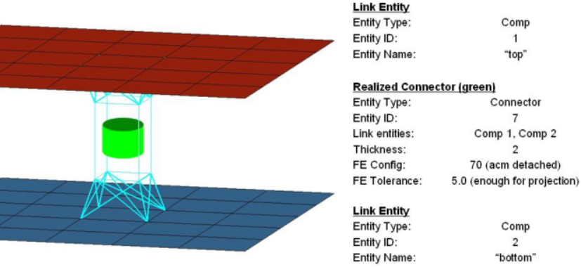
Figure 1. Connector Realization. Connector seven realized with a valid tolerance value, and a config value of type 70 (acm detached).
One advantage of separating weld FE realization from the connector definition is that a connector can be re-realized as a weld of a different configuration, or possibly, a user-defined weld, without having to redefine the connector. If you edit the connector definition, for example, add or delete a link entity from the connector, the connector removes the welds it created, and reverts back to an unrealized state. The connector is unrealized only if its user-control mode is turned off. By default, the connector mode is off but it can be turned on by registering custom FE with a connector. Connectors store all FE information that they create, allowing advanced find, mask, delete, and organizational functionality in a number of common panels. If the weld creation is unsuccessful, due to low tolerance, insufficient link entities, and so on, the connector icon is displayed as failed (red). An unrealized connector is yellow, a realized connector is green, and a failed connector is red.
Connector State
Status of the connector before and after realization.
- Unrealized
- The initial definition of the connector entity after it is created.
- Realized
- The connector is considered realized only if weld creation at the connector was successful.
- Modified
- The connector is considered modified when one or more of its corresponding attributes have been edited in the Connector Entity Editor.
- Failed
- The connector is considered failed if the weld creation at the connector was not successful.
Link Entity State
The link entity state specifies if the entity referenced by the link entity is meshed or unmeshed.
- Geom
- Specifies that the entity needs to be connected (welded) using its geometry (connect surfaces only).
- Elems
- Specifies that the entity needs to be connected (welded) using its mesh.
Both states are applicable to assemblies, components and surfaces only. The elems state connects the mesh on the assembly, component, or surface. The geom state connects the geometry on the assembly, component, or surface. For all other link entities only the elems state is applicable. The states are added to the connector entity.
After establishing link entities, they can only be modified and edited in the lower part of the Connector Browser. The functions to add link, update links and remove links is found in the browser's right-click context menu.
The link entity state options for assemblies, component, and surfaces are set when creating the connector, or on the Add Links panel. The state can be edited/updated in the lower part of the Connector Browser, as well. Therefore, the extended information has to be activated in the browser configuration.
Link Entity
A link entity is a reference to a separate entity that can be added to a connector.
The entities, or a subset of them, to which the link entities refer are welded together during realization.
- Assemblies
- Connect elements or surfaces.
- Components
- Connect elements or surfaces.
- Elements
- Facilitates a patch-patch weld connector.
- Nodes
- Facilitates a node-node weld connector.
- Parts
- Connect elements or surfaces.
- Properties
- Connect elements.
- Surfaces
- Create welds to connect geometry before meshing; the welds create fixed points for the mesh. The connected surfaces may be either meshed or unmeshed.
- Tags
- Define a weld connector for a node or an element that it holds.
After link entities are established, they can only be modified and edited in the lower part of the Connector Browser. The functions to add link, update links and remove links is found in the browser's right-click context menu.
The link entity options are set when creating the connector, or on the Add Links panel. The link entity can be edited/updated in the lower part of the Connector Browser as well.
Number of Layers
The number of layers defines how many thicknesses (layers) have to be connected at the connector position.
For seam and area connectors the number of layers is predefined as two.
For most spot connectors you will set the number of layers to two or three; though any higher number is possible. For spot connectors it is also possible to set the number of layers to auto. Then the exact number of layers is identified during the link detection and is written to each individual connector.
Bolt connectors can additionally be set to unlimited. This is for cases when the exact number of layers is not known. In this case, the number of layers is limited by other conditions like tolerance and cylinder dimensions.
For apply mass connectors a limit for entities can be set; this is optional.
- Combined connector creation/realization in the top subpanel for spots, bolts, seams and areas.
- Pure connector creation in the create subpanel for spots, bolts, seams and areas.
- Adding links in the Add links panel.
The link entity options are set when creating the connector, or on the Add Links panel. The link entity can be edited/updated in the lower part of the Connector Browser, as well.
Re-Connect Rules
Defines how a connector should protect its link entity information.
- During pure connector creation in the create subpanel for spots, bolts, seams and areas, if connect when is set to now.
- During adding links to an existing connector in the Add links panel, if connect when is set to now.
- During adding links to an existing connector in the lower part of the Connector Browser.
- None
- If a link entity references an entity that is removed from the database, the link entity is then removed from the connector.
- by id
- If a link entity references a entity that is removed from the database, the link entity retains the ID of the entity. The link entity remains in the connector.
- by name
- Same as the by id rule except that the entity name is retained.
- by UID
- Works the same as the other rules except that the part unique identifier is retained.
The link entity options are set when creating the connector, or on the Add Links panel. The link entity can be edited/updated in the lower part of the Connector Browser, as well; therefore, the extended information has to be activated in the browser configuration.