Visualization
Tools for visualizing orientations, ply shapes and ply layers.
Several types of visualization tools specific to composites are available.
Information that can be plotted includes:
- Composite part material direction
- Ply fiber and matrix directions
- Ply shape
- Ply layers of 2D model shown with thickness
Material Direction
Material direction of composite parts.
The material direction of a composite part defines the direction referenced by all ply orientations. Visualizations are performed using the Orientation Review tool.
- From the menu bar, click or select from the laminate or ply context menu.
- In the dialog, click the Material System tab.
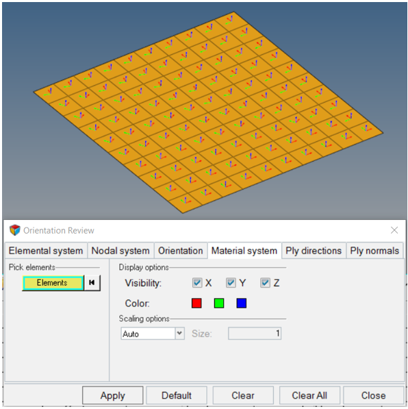
Figure 1.
Ply Direction
Visualize ply directions.
Ply directions for both nominal fibers and draped fibers can be visualized.
- From the menu bar, select .
- In the dialog, click the Ply directions tab.
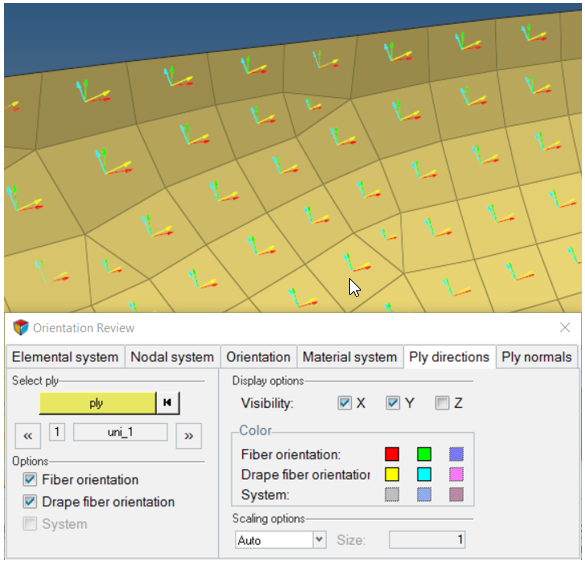
Figure 2.
Ply Shape
Visualize ply shapes.
Visualize ply shape boundaries of selected plies in the graphics area using the selector in the Model Browser.
.-
Select one or more ply entities in the Model Browser.
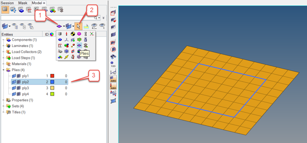
Figure 3.
Thickness and Layers
Display thickness of ply layers.
For ply-based shell models, the thickness of each ply layer can be displayed using
the visualization options at the bottom right of the graphics
area.
Note: Only
laminate thickness is supported for zone-based shell models. Ply layer
visualization is not supported. The recommended option is to use the Aerospace
Absorb Properties option to convert the zone properties to plies.
-
Set the Composite Layers control to
Composite Layers.
This will display the individual layers within each element thickness.
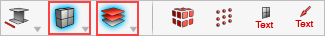
Figure 4. -
From the menu bar, select and type a factor in the ply visualization
thickness factor field. Typical values range from 5 to 10.
The thickness of each ply layer is increased.
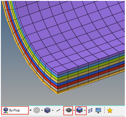
Figure 5.