Composite Browser
Use the Composite Browser to create, organize, and manage composite modeling data.
To open the Composite Browser, from the menu bar, click .
Figure 1.
The Composite Browser consolidates entities and tools used in ply-based models. Ply-based models can be created, edited and reviewed from within the Composite Browser. Additionally, composite stress toolbox functionality, such as ABD matrix calculation, is provided in the context menu of relevant entities.
Browser Interface
The Composite Browser interface.
- The top pane contains a hierarchical view of either ply-based, or zone-based composite data.
- The bottom pane contains the Entity Editor.
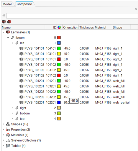
Figure 2.
Views
Composite views.
View options appear at the top of the Composite Browser.
Laminate View
- Laminates
- Plies
- Shapes (sets)
- Properties
- Materials
- System Collectors
- Tables
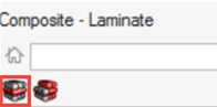
Figure 3.
- Plies can be dragged between the Unstacked Plies folder and the laminate in which they should be stacked.
- Ply order within a laminate can be manipulated by dragging one of more plies to a new location within the laminate.
- Interface Laminates and sublaminates can be defined by dragging one or more laminates into another laminate. The parent becomes an interface laminate and the children become sublaminates. For more information on this modeling technique, see Interface Laminates.
- Material, Ply and Laminate level composite stress toolbox calculations, accessed from the Analyze context menu option.
Zone View
- Laminate level composite stress toolbox calculations, such as ABD matrix calculation, accessed from the Analyze context menu option.
- Editing of orientation, thickness and material of plies passing through a zone. Any changes will propagate to all zones that contain the edited ply.
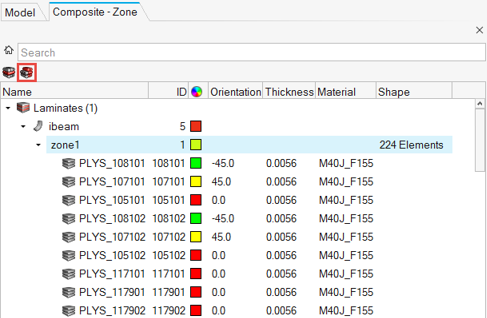
Figure 4.
Orientation Visualization
Common orientation methods.
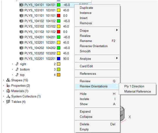
Figure 5.
- Ply 1 Direction: Displays ply 1 direction (fiber) orientations. If a drape table is assigned to the selected ply, drape corrections are included as part of the vector.
- Material Reference: Displays the x, y and z axes of the material reference orientation. This is the direction which ply orientations rotate from.
Composite Stress Toolbox
Composite stress tools functionality.
- Laminates: If plies have a shape defined by an element set, all zones of contain thickness in laminate. If one or more plies do not have shape defined, the full list of plies in the laminate is used.
- Zones
- Plies
- Materials
For more information, see Composite Stress Toolbox.
Solver-Specific Details
Details for various solvers.
Entities created in the Composite Browser are assigned the most common solver card for a typical ply-based model. Properties and Shapes are filtered based on solver card to only display appropriate cards for a ply-based model. Additionally, in the OptiStruct profile, the appropriate card is set for laminate and ply entities upon creation.
OptiStruct
| Entity | Displayed Cards |
|---|---|
| Property | PCOMPP |
| Set | SET_ELEM, None |
Radioss
| Entity | Displayed Cards |
|---|---|
| Property | PCOMPP |
| Set | SET_ELEM, None |
Abaqus
| Entity | Displayed Cards |
|---|---|
| Property | *SHELL_SECTION_COMPOSITE, with “Defined layers” unchecked |
| Set | ELSET, None |
ANSYS
| Entity | Displayed Cards |
|---|---|
| Property | SECTYPE, with TYPE=SHELL, PLIES=0 |
| Set | SET_ELEM, None |
LS-DYNA
| Entity | Displayed Cards |
|---|---|
| Property | SectShll |
| Set | Shell, None |
Nastran
| Entity | Displayed Cards |
|---|---|
| Property | PCOMPP |
| Set | SET, None |
Context Menu
Access additional composite options from the Composite Browser's context menu.