Exercise 2: Define Boundary Conditions and Loads for the Head and A-Pillar Impact Analysis
In this exercise, you will define LS-DYNA boundary conditions, loads, and contacts in Engineering Solutions. Also, you will set up the boundary conditions and load data for a LS-DYNA analysis of a hybrid III dummy head impacting an A-pillar.
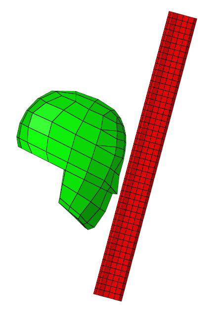
Figure 1.
Load the LS-DYNA User Profile
In this step, you will load the LS-DYNA user profile in Engineering Solutions.
- Start Engineering Solutions Desktop.
- In the User Profile dialog, set the user profile to LsDyna.
Retrieve the Engineering Solutions File
In this step, you will open the Engineering Solutions model file.
-
Open a model file by completing one of the following options:
- Click from the menu bar.
- Click
 on the Standard toolbar.
Create a Node Set
In this step, you will create a node set, *SET_NODE_LIST, which will contain all of the nodes in the head component of the model.
-
In the Solver Browser, right-click and select from the context menu.
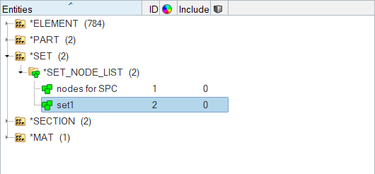
Figure 2.Engineering Solutions creates and opens a new set in the Entity Editor. -
For Entity IDs, click .
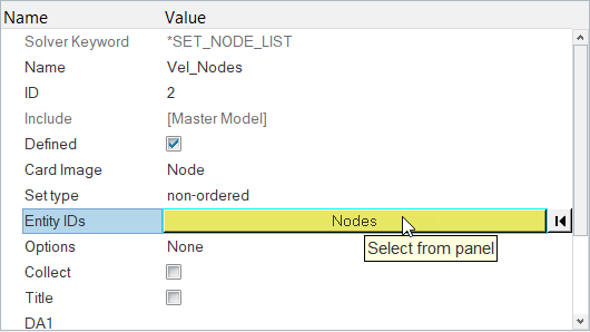
Figure 3. -
Select the head component checkbox as seen in Figure 4.
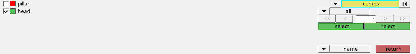
Figure 4.
Define the Velocity
In this step, you will define the velocity for the model.
-
In the Solver Browser, right-click and select from the context menu.
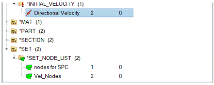
Figure 5.Engineering Solutions creates and opens a new load collector in the Entity Editor. -
For VX (x-component of mass center of velocity), enter
5.
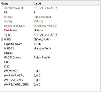
Figure 6.
Create a Load Collector
In this step, you will create a load collector for the constraints to be created.
Create Constraints on the Pillar's End Nodes
In this step, you will create constraints on the ends of the pillar component of the model.
-
Click NSID (Node Set ID) and then select
nodes for SPC.
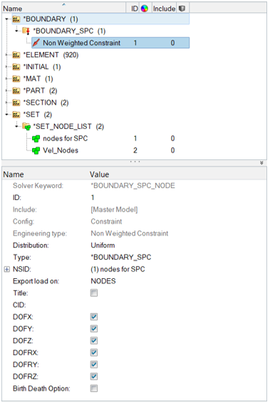
Figure 7. -
Review the Constraints created on the pillar's end nodes by right-clicking and
selecting Plot Loads and Vector in the context menu.
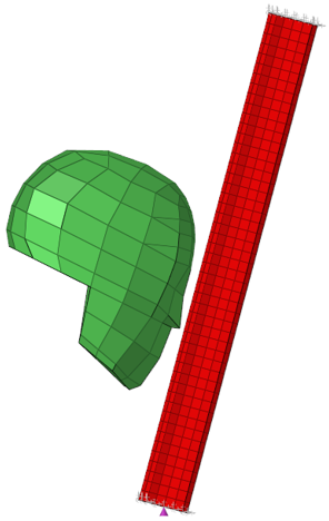
Figure 8.
Define a *SET_SEGMENT for the Secondary Entities
In this step, you will create a new contactsurf on the pillar element of the model.
-
In the panel area, set the second switch to
elems as seen in the following image.
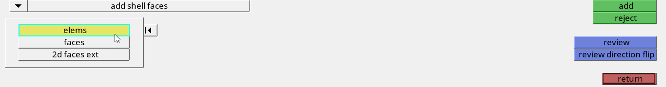
Figure 9. -
Select the pillar checkbox as seen in the following
image.

Figure 10. -
Review the contactsurf to make sure that the pyramids are pointing out of the
pillar as seen in Figure 11.
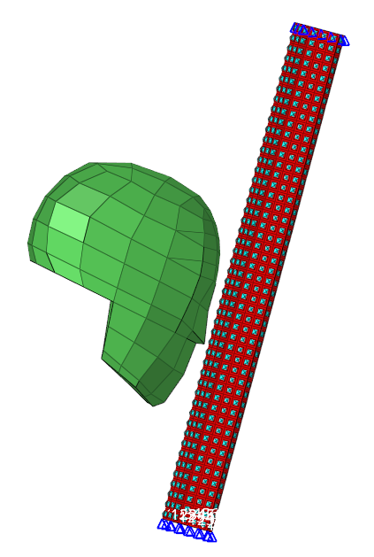
Figure 11.
Define a *SET_SEGMENT for the Main Entities
In this step, you will create a contactsurf on the head component of the model.
-
Select the head checkbox as seen in the following
image.

Figure 12. -
Review the contactsurf to make sure that its pyramids are pointing out of the
head as seen in Figure 13.
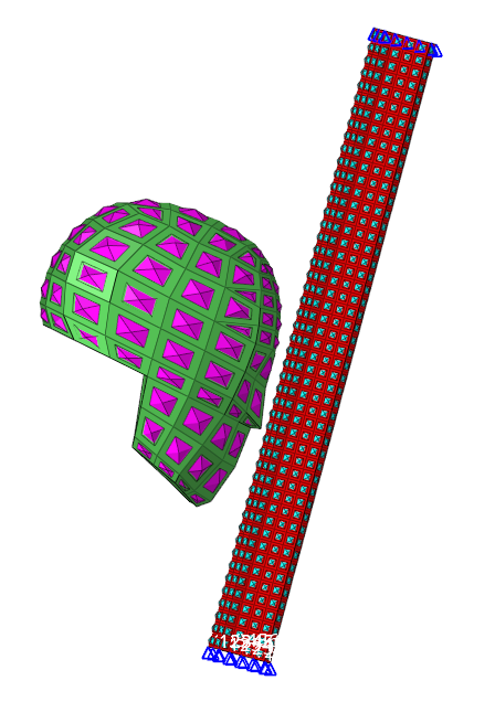
Figure 13.
Create a Engineering Solutions Group
In this step, you will create a Engineering Solutions group with the SurfaceToSurface card image.
Add the Slave and Master Contactsurfs to the Engineering Solutions Group
In this step, you will add the slave and master contactsurfs to the Engineering Solutions group.
-
In the Entity Editor, click MSID
and set the entity selector to Contactsurfs.

Figure 14.
Edit the Group card image
In this step, you will define the automatic option for the group in Engineering Solutions.
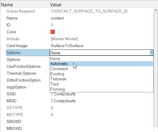
Figure 15.
Review the Group Main and Secondary Surfaces
In this step, you will review the main and secondary surfaces for the group.
-
Click interfaces from the Analysis page as seen in the
following image.
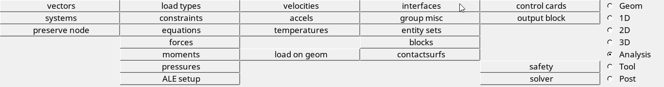
Figure 16.The Interfaces panel opens. -
Click name=, and select contact
as seen in the following image.
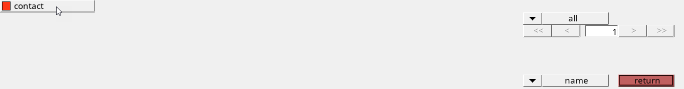
Figure 17. -
Click review.
Engineering Solutions temporarily displays the main and secondary entities in blue and red, respectively.
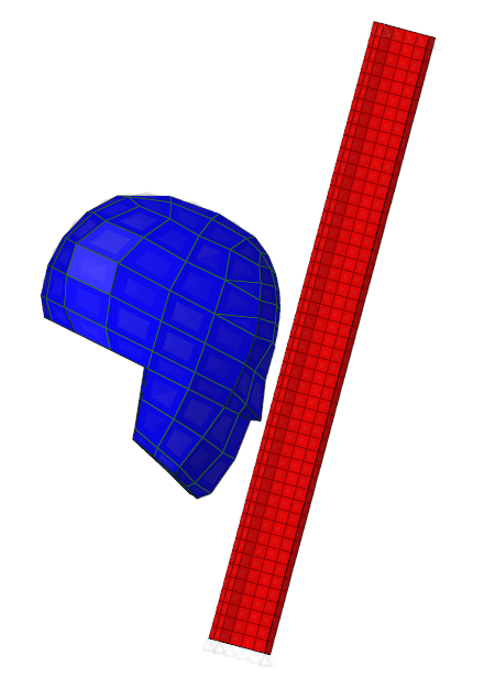
Figure 18.
Save Your Work
In this step, you will save your work in Engineering Solutions.