RD-T: 3550 Simplified Car Front Pole Impact
This tutorial demonstrates how to simulate frontal pole test with a simplified full car.
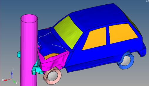
Figure 1.
- UNITS: Length (mm), Time (s), Mass (ton), Force (N) and Stress (MPa)
- Simulation time: Engine file (_0001.rad) [0 - 0.0601 ms]
- An initial velocity of 15600 mm/s is applied on the car model to impact a rigid pole of radius 250 mm.
- Elasto-plastic Material /MAT/LAW2 (Windshield)
[Rho_I] Initial Density = 2.5x10⁻⁹ ton/mm3
[E] Young's Modulus = 76000 MPa
[nu] Poisson's Ratio = 0.3
[a] Yield Stress = 192 MPa
[b] Hardening Parameter = 200 MPa
[n] Hardening Exponent = 0.32
- Elasto-plastic Material /MAT/LAW2 (Rubber)
[Rho_I] Initial Density = 2x10⁻⁹ ton/mm3
[E] Young's Modulus = 200 MPa
[nu] Poisson's Ratio = 0.49
[a] Yield Stress = 1e30 MPa
[n] Hardening Exponent = 1
- Elasto-plastic Material /MAT/LAW2 (Steel)
[Rho_I] Initial Density = 7.9x10⁻⁹ ton/mm3
[E] Young's Modulus = 210000 MPa
[nu] Poisson's Ratio = 0.3
[a] Yield Stress = 200 MPa
[b] Hardening Parameter = 450 MPa
[n] Hardening Exponent = 0.5
[SIG_max] Maximum Stress = 425 MPa
Load the Radioss User Profile
- Launch HyperMesh Desktop.
-
From the Preferences menu, select User Profiles or click
the
 icon in toolbar.
- Select Radioss (Radioss2021) and click OK.
Open the Model File
-
Click the Open Model icon
 to open the fullcar.hm
file you saved to your working directory from the
radioss.zip file.
to open the fullcar.hm
file you saved to your working directory from the
radioss.zip file.
Create and Assign the Material for Windshield
-
Input the values, as shown below:
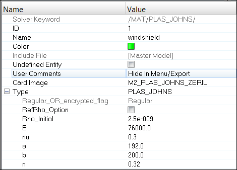
Figure 2.
Create and Assign the Material for Rubber
- Input the values, as shown below:
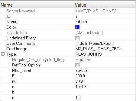
Figure 3.
Create and Assign the STEEL Material
- Input the values, as shown below:
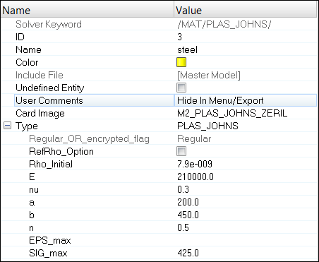
Figure 4.
Create an Infinite Plane Rigid Wall
-
Set distance d = 300.
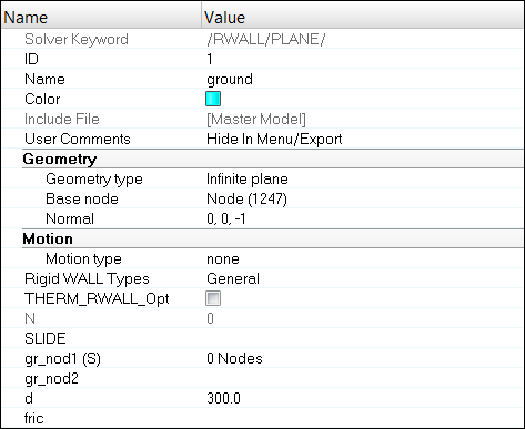
Figure 5.
Create a Cylindrical Rigid Wall
-
Set distance d= 1500.
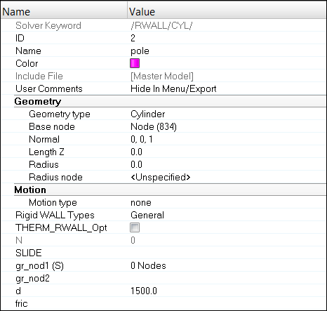
Figure 6.
Define the Self Contact (TYPE7)
- Input other parameters, as shown below.
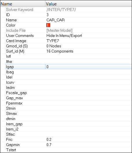
Figure 7.
Define the Contact between the Engine and Radiator (TYPE7)
- Input the values, as shown below:
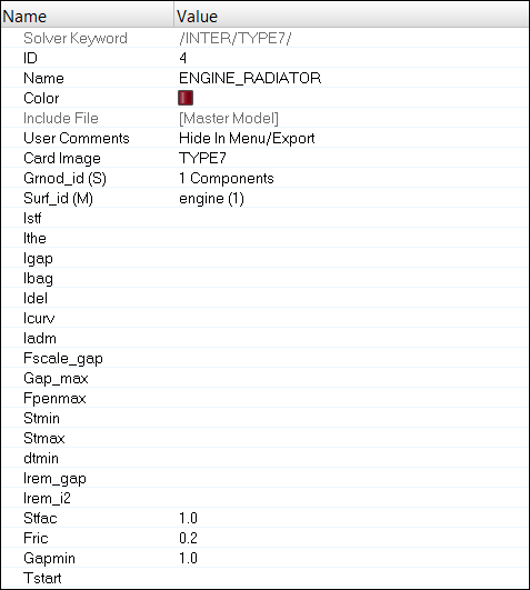
Figure 8.
Define the Initial Velocity
-
Set Vx as 15600.
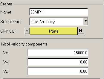
Figure 9.
Create Time History Nodes
-
For Name, enter RAIL and select the nodes on the Rail,
as shown below.
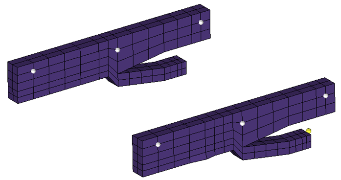
Figure 10. -
For NUM_VARIABLES, select 1 and for Data: Var, enter the
following:
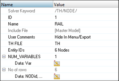
Figure 11.
Create Control Cards
- To start the Engine file assistant, select .
-
Select Create engine file and enter,
- Termination Time, enter 0.06.
- Animation output frequency, enter 0.003.
- Time history output request, enter 9e-5.
- Nodal time step, enter 0.
- Toggle Generate default output request.
Export the Model
-
Click or click the Export icon
 .
.
-
Click the folder icon
 and navigate to the
destination directory where you want to export to.
and navigate to the
destination directory where you want to export to.
- For Name, enter FULLCAR and click Save.
- Click the downward-pointing arrows next to Export options to expand the panel.
- Click Export to export the file.
Run the Model in the Solver
- Go to .
- For Input file, browse to the exercise folder and select the file FULLCAR_0000.rad.
- Click Run.
Review the Results
The exercise is complete. Save your work to a HyperMesh file. You can view the results in HyperView.