NVH Preferences
Keep all of the default configuration options and store user preferences.
NVH Preferences can also be used for all user messages in case you want to switch on the .log file creation and provide the path where it will be saved.
From the menu bar, click when the NVH user profile is loaded.
Messaging
Preference setting for all user messages in case you want to switch on the .log file creation and provide the path where it will be saved.
Module ID
Preferences to specify Subrange for Tag Points, Spoints and Plotels.
Connection ID
Preferences to force IDs the numbering pattern for connectors, so that the connection elements created after realization of the connectors fall in the defined numbering pattern. The numbering pattern currently followed is as per a typical customer case. These values may be entered in the NVH Preferences dialog in the Connection ID tab.
- To check the tagpoint coincidence during Connection Realization. This creates the necessary elements on realization of connections based on the tagpoint coincidence check.
- To apply translational only DOFs for connection realization. This creates the elements with properties only in translational direction for all connections.
- To request for connection element force output.
- Apply connection force ID.
- Max force Id size
- Maximum number of digits possible to be entered by you in the Force ID entry of the States tab in the Connection Browser.
- Size
- Number of digits of the connection ID after realization.
- Prefix
- Digit to be added as prefix to connection element ID.
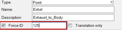
Figure 1. Forcing ID's Through the Create Connection-Interactive Tool
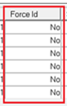
Figure 2. Forcing ID's Through the Connection Mapping Tool
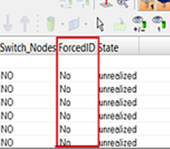
Figure 3. Forcing ID's Through the Connector Browser
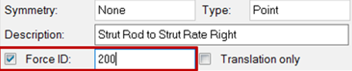
Figure 4. Forcing ID's Through the Edit Connection Tab, Which is Opened by Right-Clicking on a Connector in the Connector Browser and Selecting Edit Connection.
TagPoints
- Tolerance for node ID match during rendering
- The tolerance used for rendering the tagpoints. If the distance between tagpoints in the XML database and the FE database is more than the mentioned tolerance in the preference, tagpoints are not rendered and a message will appear.
- Global locked tagpoint Id range
- The range for locking the tagpoints outside of the module ID range.
TPL Folders
- Frequency Response
- Normal Modes
- LP
- Full Deck
- Connection
Standard Loadcases
The Standard Loadcases tab provides options to specify custom folders for defining the catalog for standard loadcases.
Version Management
The Version Management tab allows you to do data management and versioning of CAE files (assembly-XMLs, sub-XMLs and representation files). There is an option in NVH Preferences to turn ON/OFF the Version Management feature.
 Login: Enter user
credentials for Altair-One server authentication.
Login: Enter user
credentials for Altair-One server authentication. Preferences: URL for
Altair-One server.
Preferences: URL for
Altair-One server. Project Workspaces:
Dashboard for Project Workspaces.
Project Workspaces:
Dashboard for Project Workspaces.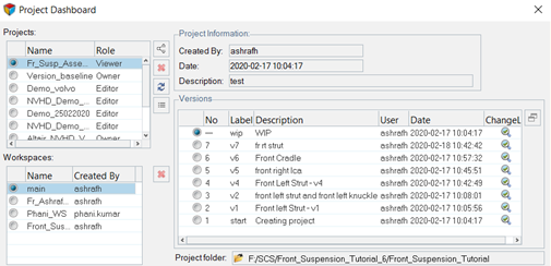
Figure 5.
Assembly Browser-Base View
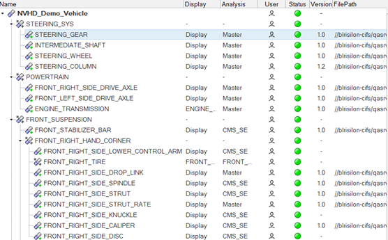
Figure 6.
Assembly Browser-File View
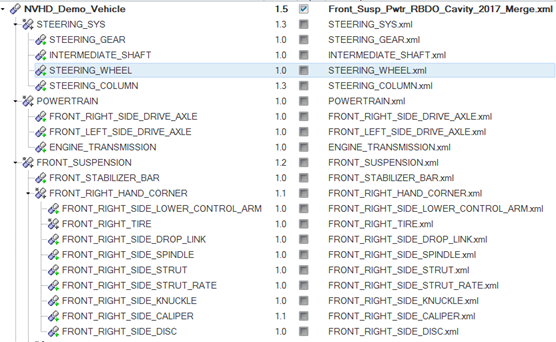
Figure 7.