Tutorial: Co-Simulating a Plunger Model with Flux 3D
Create an Activate model to regulate by hysteresis a current that feeds into the coil of a 3D Flux model of a plunger, and co-simulate the models.
The co-simulation process with Flux includes four basic steps:
- Create a Flux model (for this tutorial, the Flux model is provided for you).
- Generate the Flux coupling component required for Activate to read in the Flux model data.
- Create an Activate model and include the Flux block for reading in the Flux coupling component.
- Co-simulate the models in Activate.
Files for This Tutorial
TRANSLATING_MOTION_COUPLING.F2STA, TRANSLATING_MOTION_COUPLINGF2STA.FLU, Translating_motion_coupling.scm
Overview of the Flux Translation Motion Model
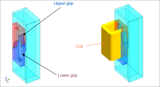
The Flux model is a plunger with one transient computation completed for the position of the plunger in a function of time. The coil of the plunger is supplied with constant voltage.
- Upper grip
- Lower grip
- Coil
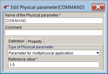
The inputs for the plunger are defined as multi-physical parameters and include:
- Command: the control of the switch
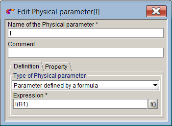
- I: the current in the coil conductor
The outputs for the plunger are scalar I/O settings that retrieve values through the sensors, formulas (forces and couples) and parameters (position, speed, acceleration).
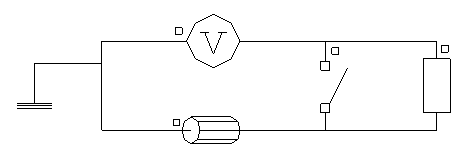
The circuit of the plunger is configured with a voltage source, coil conductor, resistor and switch.
Generating the Coupling Component in Flux
Load the Flux model and generate the coupling component with the required inputs, outputs and parameters.
-
Launch Flux, and from your working directory, open the project,
TRANSLATING_MOTION_COUPLING.F2STA.
The model loads and looks something like this:
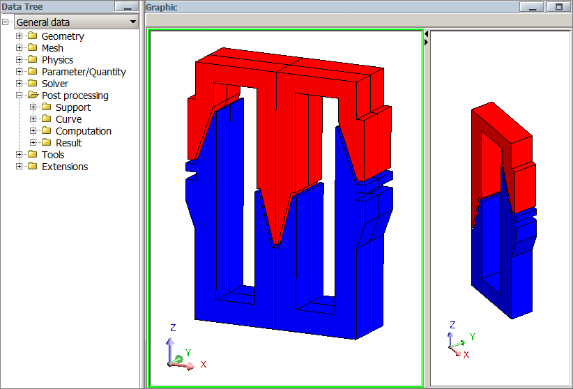 Figure 2. Split View of Plunger
 -
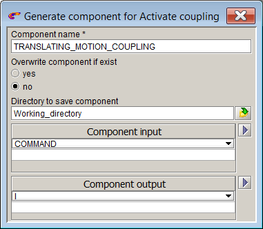
In the dialog, enter the following information for the component:
- Enter the name for the component: TRANSLATION_MOTION_COUPLING.
- Enter the path to your working directory: <name_without_spaces>.
- Select the input (geometric I/O parameters) for the component: COMMAND
- Select the output: I.
The dialog should look something like this:
Creating the Activate Model
Create an Activate model to regulate by hysteresis the current in the coil that feeds the Flux model of the plunger.
-
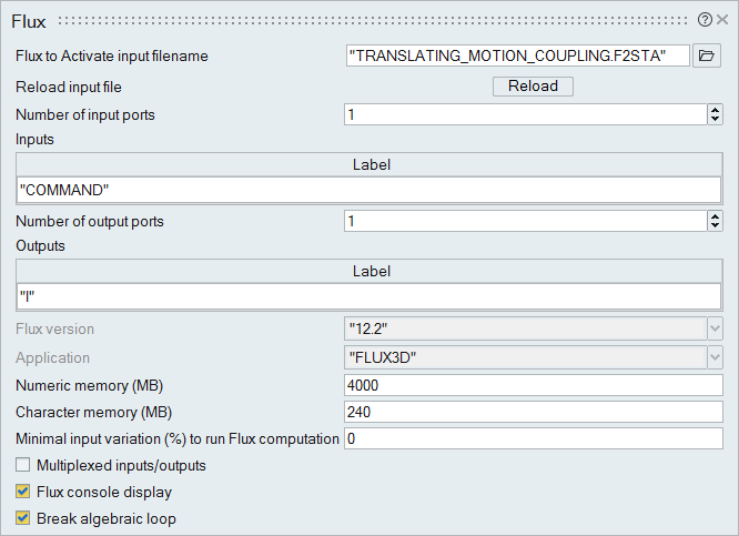
Click OK.
The Flux block dialog should look something like this:
-
In the diagram, add and define these blocks:
Add blocks Define the block options with these values Time Default Display 1 Default Display 2 Default Display 3 Default Scope 1 Default Scope 2 Default Gain Gain = -1 Hysteresis 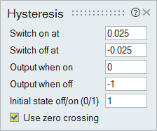
Sum Number of inputs = 2 Step Generator Step time = .07
Initial value = 1
Final value = .075
-
Assemble and connect the blocks as you see in the following figure, then save
the model.
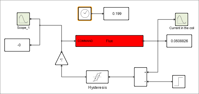 Figure 3. Diagram Assembled with Flux Block
The Activate model is complete and configured to supply a current to the Flux model of the plunger.
Co-Simulating the Activate and Flux Models
During co-simulation, the Activate model supplies a current into the coil of the plunger.
-
On the ribbon, hover over the Simulation tool group
 and select Setup
 .
.
-
On the ribbon, select Run
 .
The scopes in the Activate model plot the simulation results of the current fed into the coil of the plunger.
.
The scopes in the Activate model plot the simulation results of the current fed into the coil of the plunger.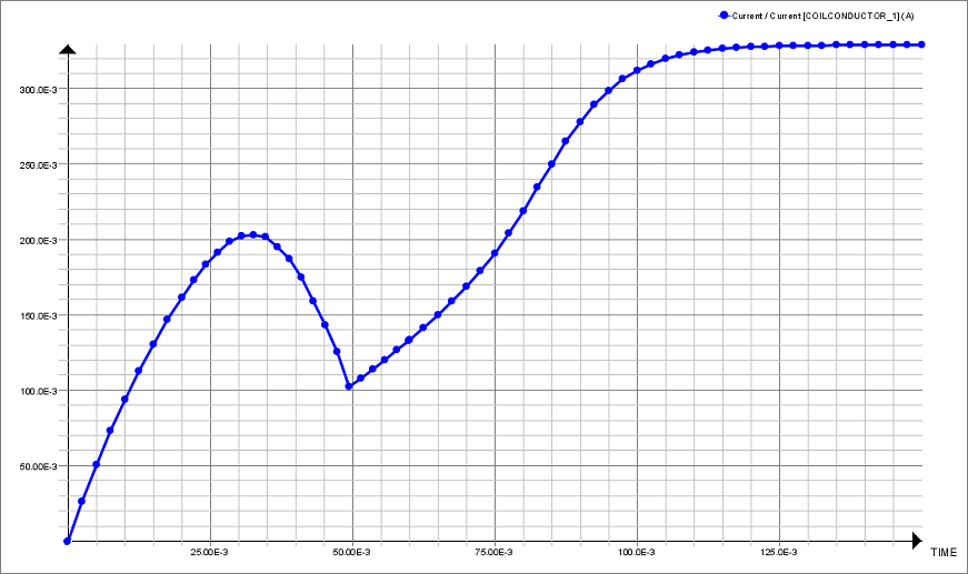 Figure 4. Current/Coil Conductor_1 (A) Without Regulation
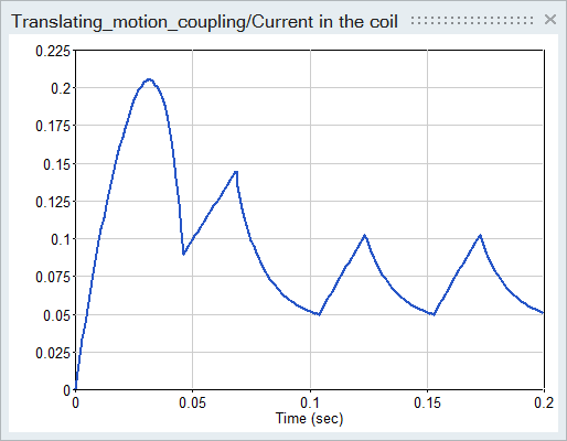 Figure 5. Current Coil Conductor With Regulation