View Near Field
This option can be used to present in a 3D View the value for each user defined observation points.
After selecting this option, the following panel will be displayed.

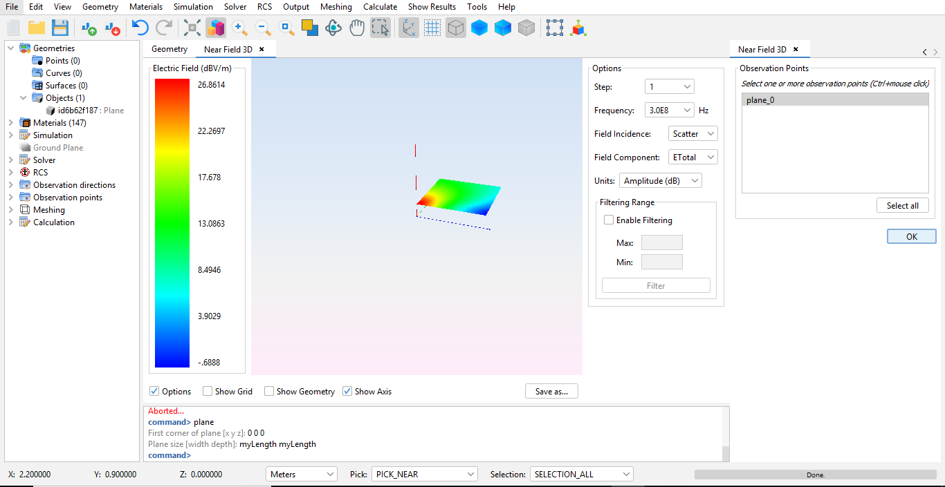
Figure 1. View Near Field panel
The diagram shows, for every structure defined as an observation point, the near field measurement in every point of the structure. For each geometry, values will be rendered with a diferent color that is smoothed, creating a grid matrix where every observation point is assigned to a color. Colors are part of a measurement system where blue is asigned to the lowest values and red to the highest values.

Figure 2. Near Field diagram
The following options are available:
- Incidence: possible values are scatter incidence, direct incidence or total incidence.
- Magnitude: which units to use in measurements. Units affect to the color scale being used.
- Field Component: which field component to inspect, from either the E-field or the H-field, and whether to inspect the X, Y or Z component or the total field.
- Filtering Range: if filtering is enabled, a custom range can be set in the measurement system, setting maximum and minimum values in the rendering view to the values provided by the user.
Additionally, the following options are available at the bottom bar:
- Options: hides and shows the options panel that appears on the left.
- Show Grid: if this option is selected, a grid with every observation point will be overlayed to the rendered figure, making possible to precisely see which value has every observation point defined in the geometry.
- Show geometry: use this option to make the geometry visible or not.
- Show Axis: use this option to hide or show the axis.
It is also possible to export a graphical representation of the image. Press Save as... to save the image as a PNG file.