View and redefine contacts, and create fasteners including nuts and bolts, screws,
and grounded bolts.
In this lesson you will learn how to:
View and define contacts
Find single and aligned holes
Automatically create fasteners
Create nuts and bolts
Create screws
Ground bolts
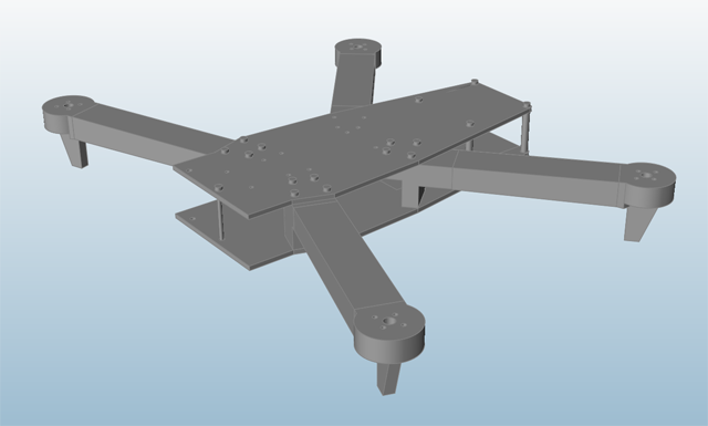
Open the Quadcopter Model
Press F7 to open the Demo Browser.
Double-click the Quadcopter.stmod file to load it in the
modeling window.
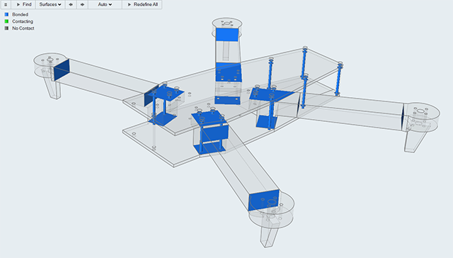
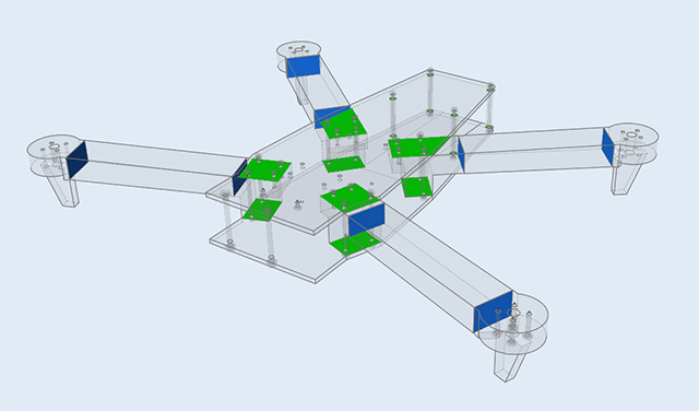
View Contacts
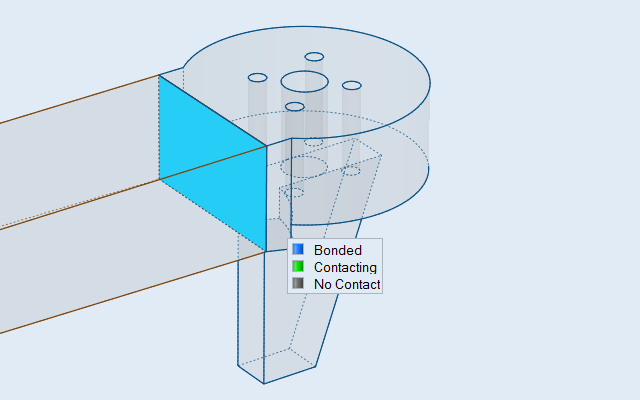
Select the Contacts tool on the Structure ribbon.
Observe as the guide bar appears, and the tool automatically finds locations
where parts are in contact.
The number of contacts found is displayed in a counter above the Contacts
icon.
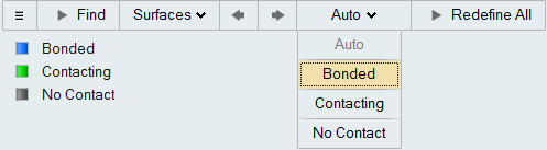
Bonded contacts are shown in blue, and contacting contacts are shown in
green. By default, if there are fasteners or joints connecting two neighboring
parts together, they are assumed to be Contacting; otherwise, they are set to
Bonded. In this example, there are no fasteners or joints present, so all of the
contacts are assumed to be bonded.
Right-click and mouse through the check mark to exit, or double-right-click.
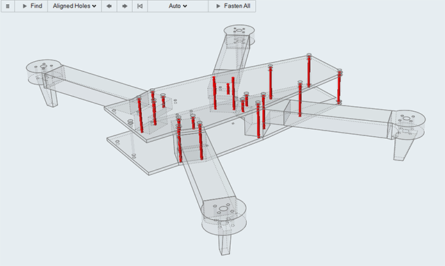
Find Aligned Holes
Now let's start creating some fasteners to connect parts that are in
contact.
Select the Fasteners tool on the Structure ribbon.
Observe as the guide bar appears, and the tool automatically finds locations
where fasteners can be placed and highlights them in red.
Make sure that Aligned Holes is selected on the guide
bar.
This will filter the results so that only aligned holes on neighboring parts
are found, rather than single holes.
The number of aligned holes is displayed in a counter above the
Fasteners icon.
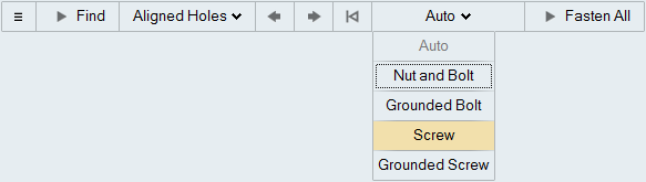
Make sure that Auto is selected on the guide bar.
When Auto is selected, Inspire will automatically place
nuts and bolts in through holes and screws in blind holes when fasteners are
created.
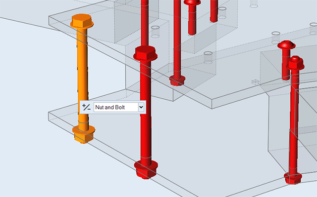
Create a Nut and Bolt
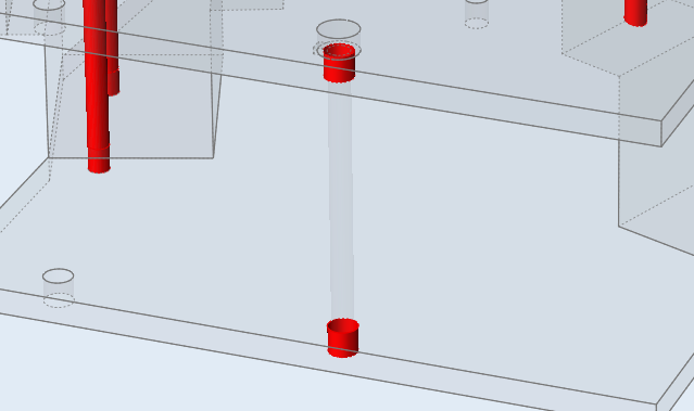
Zoom in on the front of the quadcopter.
Note that the existing geometry in this set of aligned holes is now
transparent.
When we create a fastener at this location, the original geometry will be
hidden and configured off, meaning it will no longer be included in analysis and
optimization calculations.
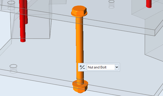
Click on one of the holes to create the fastener.
Since this is a through hole, Inspire
automatically creates a nut and bolt.
Add Fasteners
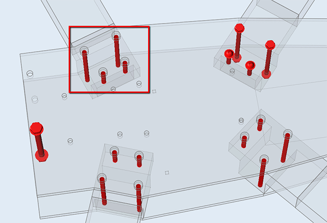
Pan and zoom in on the arm of the quadcopter shown below:
Click on the top two holes.
Inspire automatically creates nuts and bolts, as
these are through holes.
Click on the bottom two holes.
Inspire automatically creates screws, as these
are blind holes.
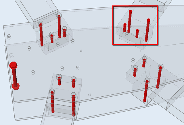
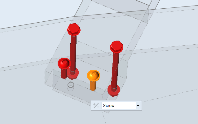
Pan and zoom in on the arm of the quadcopter shown below:
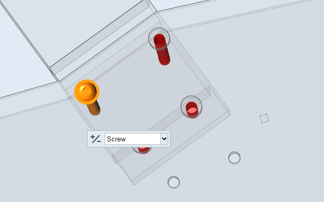
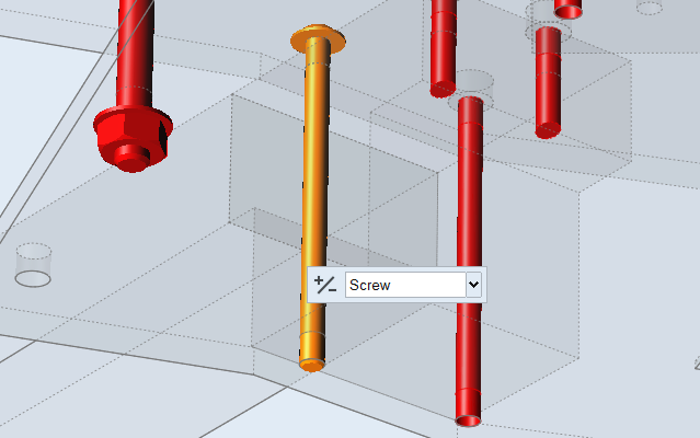
This time, we want to override the automatic settings and create a screw in a
through hole. To do this, click Auto on the guide bar and
select Screw.
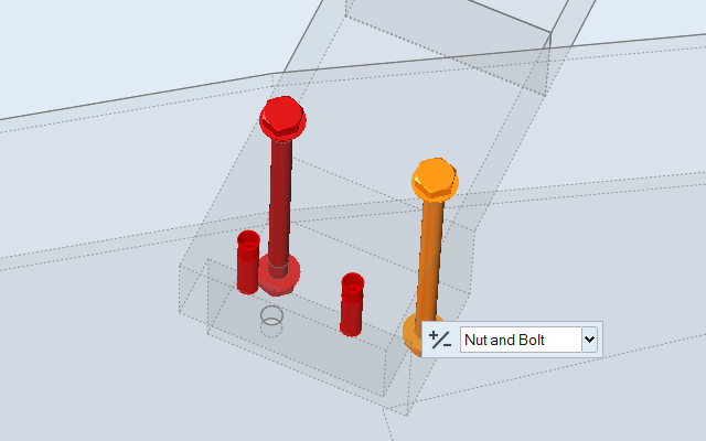
Click on the hole shown below to create the screw.
Note how there is no nut on the underside of the screw we just created, while
there is on the underside of the bolt.
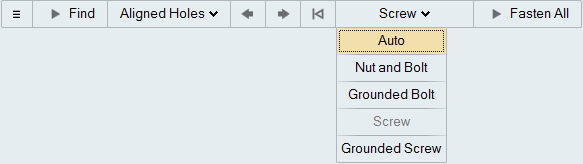
Automatically Create Fasteners
Now let's quickly create fasteners in the rest of the aligned holes.
Click Screw on the guide bar and select
Auto.
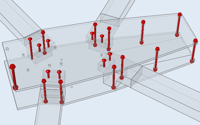
Click the Play button on the guide bar.
Inspire automatically places nuts and bolts in
through holes and screws in blind holes.
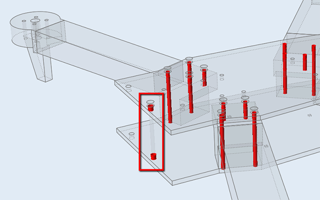
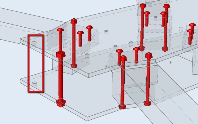
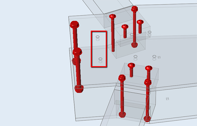
Note that no fastener was created at the location shown below, since
Inspire did not recognize the holes as aligned.
To manually create the fastener, select the inner surface of each hole, then
click again to create the nut and bolt.
Create Grounded Bolts
Next, let's create a few additional bolts that are grounded.
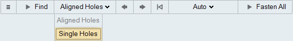
Click Aligned Holes on the guide bar and select
Singe Holes.
For single holes, Inspire will automatically create
nuts and bolts by default.
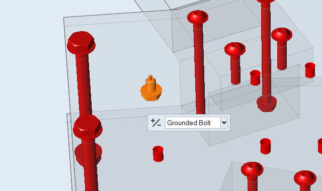
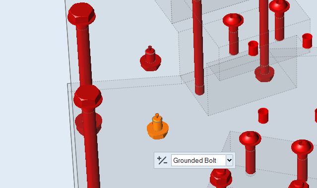
Pan and zoom in on the two holes shown below:
Click the top hole to create a grounded bolt, then click the
+/- button on the microdialog to reverse the
direction.
Repeat to create and reverse the direction of the second bolt.
Your model should look like this:
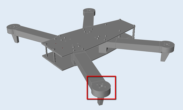
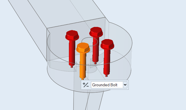
Pan and zoom in on the location shown below:
Create four more grounded bolts in the outer holes.
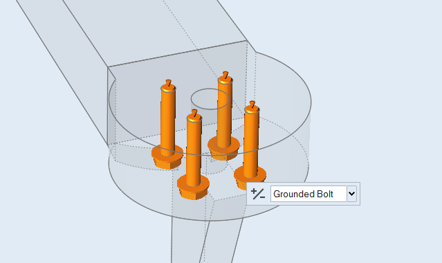
Box select the bolts and click the +/- button on the
microdialog to reverse the direction of all four bolts.
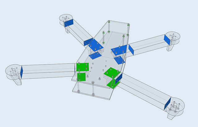
Redefine Contacts
Zoom out and select the Contacts tool.
Note that now, locations where parts are connected using fasteners appear
green, indicating that they are Contacting rather than Bonded.
If needed, you can select individual contacts and change their type.
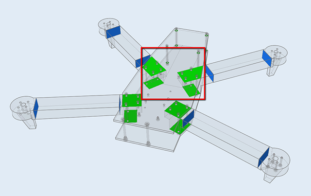
For example, hold down the Ctrl key and select the four
green contacts highlighted below:
Click Auto on the guide bar and select
Bonded.
Click Redefine Selected Contacts on the guide bar.
The selected contacts are now bonded and appear blue.
Click the arrow keys on the guide bar or keyboard to move from one contact to
another on your model.
Click a contact to select it, then select a different option in the microdialog
to change the type.
Right-click and mouse through the check mark to exit, or double-right-click.
Note: Joints such as pins and sliding pins can be created by using the Joints tool on
the Structure ribbon. The process is very similar to creating fasteners.