Set Simulation Parameters

Before executing a simulation, you can define parameters for simulation time, zero-crossing and solvers.

Setting Simulation Time

Define a variety of time parameters for your simulation requirements.

  1. On the ribbon, hover over the Simulate tool group, and click the simulation parameters tool:
  2. On the Simulation Parameters dialog that appears, select the tab, Simulation Time. Define the options as required for your simulation:
    For parameter Do this
    Initial time Enter a value to start the simulation.
    Final time Enter a value to end the simulation.
    Tip: You can also define Final Time by adding an End block to your diagram. The End block includes a parameterized simulation time.
    Real time scaling Enter a value to scale and insert a delay into the simulation time. For example, if you enter 0 (zero), the real time is ignored and the simulation runs as fast as possible; if you enter 1, one unit of the simulation time = 1 second; if you enter 10, one unit = 10 seconds.
    Tolerence on time Enter a value to define the acceptable error between event times. The value for the Tolerance on Time lets the Simulator ignore the very small time differences between event times.

Tolerance on Time

A parameter for comparing time quantities.

Tolerance on time is an advanced setting for comparing two time quantities. Some applications for this parameter include detecting:

  • When the difference between the simulator time and an event is less than the tolerance threshold.
  • Two time events that are very close together. For example, if the difference between the instants of several time events is less than the time-tolerance, the time events are considered as simultaneous.
  • A zero-crossing, in which case the software stops the iteration when the difference between the time instants of the right- and left-hand sides of the zero-crossing is less than the tolerance threshold.

Tolerance Options

Tolerance on Time is a value computed dynamically as a function of the current simulation time and the machine’s epsilon. If this value is very low or very high, simulation problems can occur. Changing the value depends on the model and requested error tolerance. Generally, if you choose a loose error tolerance, the zero-crossing surfaces need not be precisely detected. If the value is set to auto, and the simulation fails, enter a low value such as 1e-14, and then gradually increase the value as required.

Setting Zero Crossing

Define this advanced parameter to handle discontinuities or generate events.

  1. On the ribbon, hover over the Simulate tool group, and click the simulation parameters tool:
  2. On the Simulation Parameters dialog that appears, select the tab, Zero Crossing, and define the options as required for your simulation.

    The zero-crossing detection mechanism has a threshold to avoid chattering or repeated zero crossings during a model simulation. When detected, the zero crossing is considered as zero until the absolute value of crossed surfaces becomes greater than the zero-crossing threshold. The value of the zero-crossing threshold can be user-defined or computed dynamically by the simulator using the partial derivatives of the zero-crossing surfaces. The Tolerance on Time option stops the zero-crossing detection when the difference between the left- and right-hand side of the zero crossing becomes less than this threshold. If the Tolerance on Time option is set to auto, the global time threshold is applied.

    For more information about the zero-crossing parameter, see the chapter, Altair Activate Hybrid Simulator and Interface with Numerical Solvers in the Extended Definitions.

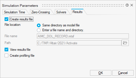
Creating a Results File

Capture and review simulation results including the signals of all the blocks in a model.

  1. After loading a model, on the ribbon, hover over the Simulate icon, and click the Simulation Parameters:
  2. On the Simulation Parameters dialog, select the Results tab.
  3. Select the Create results file option.
  4. For File location, select an option to save the results file:
    • Same directory as model file. When you select this option, the file is automatically named after the model.
    • Enter a file name and directory. If you select this option, enter a file name and path in the corresponding fields.
  5. To automatically launch the Results File Viewer and open the .mtsf file after the simulation is completed, select View results file.
    Note: Alternatively, from the ribbon, select Tools > Results Viewer, then navigate to the file from the viewer.
  6. Select OK.