Physical Component Modeling
Learn about modeling physical components.
Signal Versus Physical Component Diagrams
The process of modeling dynamic systems includes assembling blocks that exchange data through a network of input and output ports. Though possible to model physical systems with the basic Activate blocks, the process requires translating into explicit form the implicit equations that represent the behavior of the physical components. In addition, the resulting diagrams have an unconventional appearance compared to component-based diagrams as you can see in the following figure.
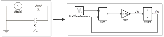
Figure 1. Component-Based Diagram (left) and Activate Diagram (right)
The fundamental reason why regular blocks are not well-suited for modeling physical components is that component ports are connectors which, unlike block ports, need not be specified as inputs or outputs. A component places general constraints on its port signals. For example an electrical resistor specifies relations between the currents and voltages on its ports, in particular that the sum of currents flowing in is zero and the difference of voltages is proportional to the current, but the component does not require any current or voltage to be an input or output.
Benefits of Modeling with Implicit Blocks
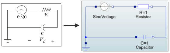
Figure 2. Conventional Diagram (left) and Activate Diagram with Implicit Blocks (right)
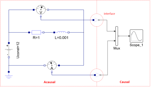
Combining Component and Block Models
A component model and block model can be interconnected using special interface blocks as you see in the following diagram:
Additional information on modeling physical components is available in the Extended Definitions for Advanced Users.