5G Network Analysis
There are three simulation approaches when analyzing 5G networks.
5G_FDD or 5G_TDD, that triggers a few
small but essential changes. The most important changes are related to simulation
strategies to deal with antenna-pattern information.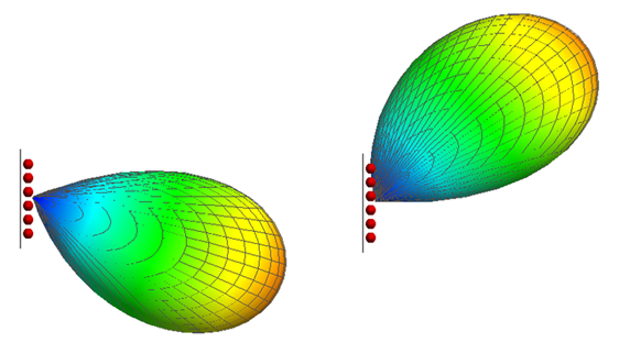
Figure 1. Examples of beam patterns achieved with phased arrays at a base station (top view).
- with isotropic antennas
- with envelope antenna patterns that represent a set of possible beams
- with individual beams
Simulation Based on Isotropic Base-Station Pattern
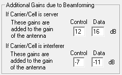
Figure 2. Example of beamforming gains added to an envelope pattern in a 5G project on the Carrier dialog.
For a given mobile station, one base station antenna is the server, and the other ones are interferers (if they use the same carrier frequency). The server points its beam to the mobile station, so the expected beam gain to be added to the isotropic antenna is positive. The interferers are serving their own mobile stations and are likely to be pointing their beams in other directions, at least most of the time. Therefore, the gain to be added to those antennas is likely to be small and may be negative.
Simulation Based on Envelope Antenna Pattern
The second possible approach is to simulate with the envelope antenna pattern (see Figure 3) of all possible beams. This assumes that, if a mobile station is in the cell, the base-station array directs its best beam at that mobile station. For that mobile station, the gain of the envelope pattern equals the gain of the specific beam, so the propagation result is correct.
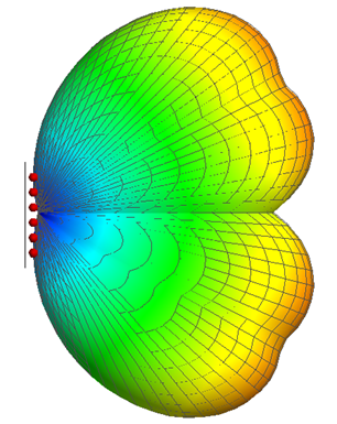
Figure 3. Envelope antenna pattern for a set of four beams (usually the set would be larger).
All mobile stations in the same cell receive the best beam for their location, so the envelope pattern provides correct propagation results. Individual mobile stations in the cell may operate on different sub-carriers or be served in different time slots.
For interference from other cells, the gain of the envelope antenna pattern of the interfering cell has to be corrected, because an envelope pattern (in the simulation) will send more power into neighboring cells than one beam (of an actual base station) would. This correction is specified in ProMan during carrier assignment when using an envelope pattern, see Figure 4.
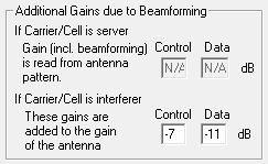
Figure 4. Example of beamforming gains added to an envelope pattern in a 5G project.
To provide values for additional gain in the interfering case is not hard science. There will be occasional time slots where a narrow beam from an interfering cell points right at a mobile station in a serving cell (correction would be 0 dB, worst case). There will also be more time slots where an interfering beam points in a completely different direction (correction would be -20 dB or lower; only minor interference). The default values of -7 dB and -11 dB are seen as a time average of the occasional worst case and the more-frequent cases where the interfering beam points elsewhere.
Simulation Based on Individual Beams
The final possible approach is to simulate with individual beams, see Figure 1. Since this requires knowledge of where the mobile stations are, this is usually combined with a Monte-Carlo analysis. When setting up a Monte-Carlo analysis, the offered traffic, which can be location-dependent and service dependent, is specified. During the Monte-Carlo analysis, ProMan generates snapshots with semi-random distributions of mobile stations to be served and performs the network analysis for each snapshot. Since the beams are known, no additional gains due to beamforming need to be specified (contrary to the approaches with omni-directional patterns and with envelope patterns).
Antenna Masking in Network Planning
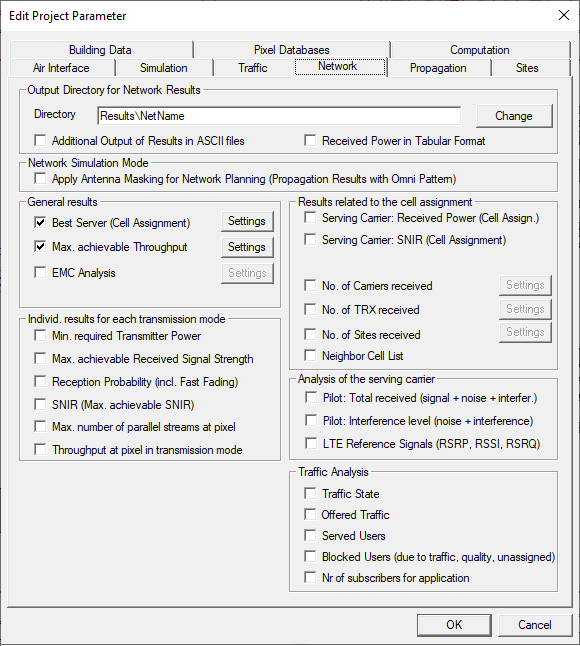
Figure 5. The Edit Project Parameter dialog, Network tab.
- Propagation simulation is performed, and results displayed, with an omni-directional (isotropic) pattern.
- Network planning is performed by adjusting propagation results based on actual antenna patterns for control and for data. These could be envelope antenna patterns or individual beams.
- Propagation simulation is performed with one antenna pattern.
- Network planning is based on one antenna pattern for both control and for data.
Masking mode is necessary for Monte Carlo simulations with individual beams, and is useful for simulations with envelope patterns when those for control and for data differ significantly. Traditional mode is attractive for simulations with envelope patterns when the patterns for control and for data do not differ significantly. In the latter case, the display of the propagation results are more informative. In both masking mode and traditional mode, only one propagation simulation per antenna is performed.