Feeder Cables
Feeder cables can be drawn by the user and assigned to a transmitter.
The attenuation of a cable is determined automatically depending on cable length and loss per 100 meter. The attenuation is applied as “cable loss” for the selected transmitter.
Drawing of Cables
Click to draw a cable. It is possible to draw cables only in network planning projects, not in pure propagation projects. After selecting the draw mode, the user can draw a poly line. The poly line can be completed with the right mouse button. After completion the following dialog appears in which the settings of the cable can be defined:
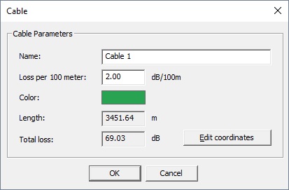
Figure 1. The Cable dialog.
With the button Edit coordinates the coordinates (for example, z coordinate) can be modified manually.
Management of Cables
Cables can be modified and deleted with the menu item . The dialog window shows all cables defined in the current project together with the most relevant information. It is also shown the transmitter to which a cable is assigned. If the cable is assigned to several transmitters only the first transmitter is shown in the table. The assignment of cables to transmitters can be done in the transmitter dialog.
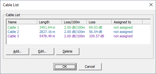
Figure 2. The Cable list dialog.