Pattern of Single Antennas Used in MASC
For each antenna used in the configurations, a far field radiation pattern is available. This pattern is measured in an anechoic chamber and does not include, usually, any masts, arms or walls. Only the radome of the antenna is included. If the antenna consists of multiple dipoles, the pattern describes the radiation of the superposed signal radiated from all dipoles. An isolated analysis of a single dipole is not possible. The radiation is concentrated in a single point – even if multiple dipoles are used to build the antenna.
The pattern is provided by the manufacturer of the antenna, and it is either 2x2D (horizontal and vertical plane) or real 3D (see Figure 1 and Figure 2). It is possible to compute the 3D pattern based on the vertical and horizontal 2D patterns. Figure 2 shows an example of such a 3D pattern based on the patterns shown in Figure 1.
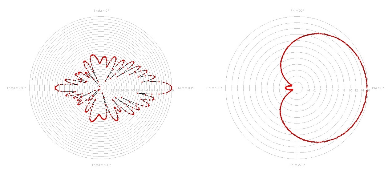
Figure 1. Vertical (left) and horizontal (right) antenna pattern (Antenna Kathrein K739856).
MASC always works with 3D patterns of every single antenna used in the configuration. If the 3D pattern is not available, it is interpolated with the HPI algorithm.
The shielding of the radome of an antenna is obviously not considered in its radiation pattern – but for all other antennas of the configuration. The influence of mast, arms on the radiation pattern is considered for each antenna.
The gain of the antenna can either be relative to an isotropic radiator (values in dBi) or on a half-wave dipole (values in dBd). The conversion between both values is possible with the gain of the half wave dipole (2.1 dBi).
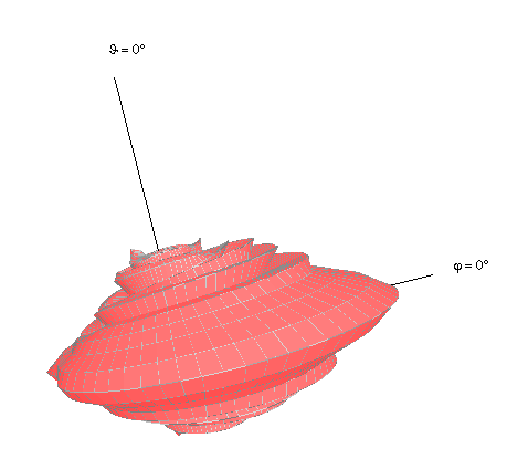
Figure 2. Interpolated 3D Antenna Pattern (Antenna Kathrein K739856).