Wall Configuration (For Example, Antenna in Front of a Wall)
The wall configuration can be used, if the antennas are mounted at or in front of a wall. Often only one antenna is mounted – but in MASC the number is only limited by the RAM.
The wall configuration consists at least of an antenna, the arm to mount the antenna and a wall.
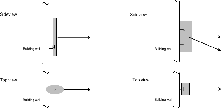
Figure 1. Example for wall configuration.
The wall configuration considers shadowing of the wall as well as reflections on the wall. If the transmission / penetration loss of the wall is very high, the radiation in the direction of the wall is suppressed.
Important is the consideration of the reflection at the wall because the reflected rays are superposed to the direct rays and depending on the phase difference between the two rays, the superposed signal can be decreased or increased (see Figure 2).
In this configuration very often only one antenna is considered. Of course, the software itself can handle an arbitrary number of antennas. In the case of multiple antennas, the orientation of the wall is defined with the first antenna in the list of antennas.
The computation of one reflection is sufficient to obtain the required accuracy.
The size of the wall is assumed to be infinite, so diffractions at the wedges of the wall are neglected.
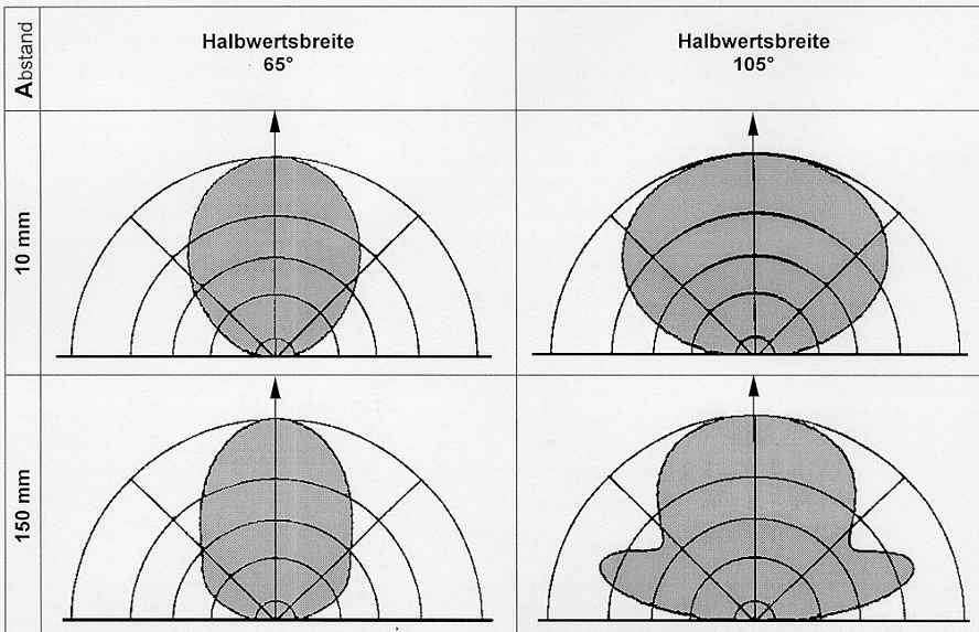
Figure 2. Influence of wall on antenna pattern of a GSM 900 directional antenna. The distance between antenna and wall is 100 mm for both figures in the upper row and 150 mm for both figures in the lower row.
The wall configuration considers the following parameters:
- Number of (single) antennas considered: arbitrary (depends on RAM)
- Antenna
- Antenna type: directional (sector) antennas or omnidirectional antennas
- Pattern of single antenna can be loaded from a file
- Wall
- Size of wall
- Material of wall (reflection and transmission loss)
- Arms at mast
- Diameter and length of each arm as well as height where the arm is mounted at mast
- Material of arm (reflection and transmission loss)
- Azimuth of the arm [0°..360°]
- Azimuth of the antenna [0°..360°, relative to arm] (0° is equal to the direction of arm)
- Elevation (tilt) of the antenna [-90°..90°]
- Radome
- Size and type (rectangular, circular) of the radome
- Material of radome (reflection and transmission loss)
- Electrical parameters
- Power splitter: relative split between antennas must be defined (for example, 1:1:2:1).
- Phase shifter: phase shift between antenna can be defined.