LoRaWAN Overview
LoRaWAN Network Fundamentals
(Most of the information here is reproduced from the Semtech LoRa Developer Portal)
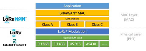
Figure 1.
LoRaWAN Network Elements: An Introduction
Now that we have a basic understanding of LoRa, we will examine the architecture of a LoRaWAN network.
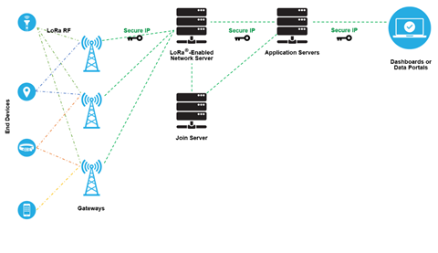
Figure 2.
Let us examine this diagram in smaller pieces.
LoRa-based End Devices
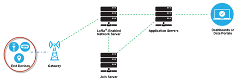
Figure 3.
In the majority of applications, an end device is an autonomous, often battery-operated sensor that digitizes physical conditions and environmental events. Typical use cases for an actuator include: street lighting, wireless locks, water valve shut off, leak prevention, among others.
When they are being manufactured, LoRa-based devices are assigned several unique identifiers. These identifiers are used to securely activate and administer the device, to ensure the safe transport of packets over a private or public network and to deliver encrypted data to the Cloud.
LoRaWAN Gateways
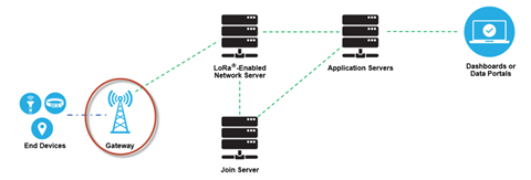
Figure 4.
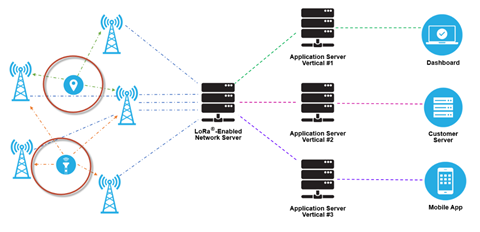
Figure 5.
Furthermore, LoRa allows for scalable, cost-optimized gateway implementation, depending on deployment objectives. For example, in North America, 8-, 16-, and 64-channel gateways are available.
The 8-channel gateways are the least expensive. The type of gateway needed will depend on the use case. Eight- and 16-channel gateways are available for both indoor and outdoor use. Sixty-four channel gateways are only available in a carrier-grade variant. This type of gateway is intended for deployment in such places as cell towers, the rooftops of very tall buildings, etc.
Network Server
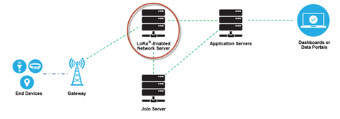
Figure 6.
- Device address checking
- Frame authentication and frame counter management
- Acknowledgements of received messages
- Adapting data rates using the ADR protocol
- Responding to all MAC layer requests coming from the device,
- Forwarding uplink application payloads to the appropriate application servers
- Queuing of downlink payloads coming from any Application Server to any device connected to the network
- Forwarding Join-request and Join-accept messages between the devices and the join server
Application Servers
Application servers are responsible for securely handling, managing and interpreting sensor application data. They also generate all the application-layer downlink payloads to the connected end devices.

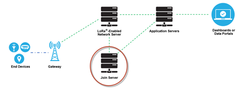
Figure 7.
Join Server
The join server manages the over-the-air activation process for end devices to be added to the network.
- DevEUI (end-device serial unique identifier)
- AppKey (application encryption key)
- NwkKey (network encryption key)
- Application Server identifier
- End-Device Service Profile
LoRaWAN Network Elements: Device Commissioning
For the sake of security, quality of service, billing, and other needs, devices must be commissioned and activated on the network at the start of operation. The commissioning process securely aligns each device and the network with respect to essential provisioning parameters (such as identifiers, encryption keys, and server locations).
The LoRaWAN specification allows for two types of activation: Over-the-Air Activation (OTAA) (preferred) and Activation by Personalization (ABP).
LoRaWAN Network Elements: Security
There are two key elements to the security of a LoRaWAN network: the join procedure and message authentication. The join procedure establishes mutual authentication between an end device and the LoRaWAN network to which it is connected. Only authorized devices are allowed to join the network. LoRaWAN MAC and application messages are origin-authenticated, integrity-protected and encrypted end-to-end (i.e., from end device to the application server and vice versa).
- Network traffic has not been altered
- Only legitimate devices are connected to the LoRaWAN network
- Network traffic cannot be listened to (no eavesdropping)
- Network traffic cannot be captured and replayed