Tutorial: Motion Joint Couplers
Add couplers to joint pairs, reverse the direction of a coupler, then run a motion analysis and plot the results.
In this lesson you will learn how to:
- Add couplers to joint pairs
- Reverse the direction of a joint coupler
- Run a motion analysis and plot the results
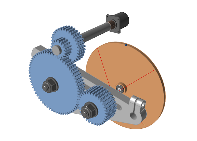
Open the Inspire Model
-
Double-click the M08_SpurGearset.stmod file in the Motion
folder to load it in the modeling window.
Run a Motion Analysis
-
Click the Quick Run button on the Analyze Motion tool to
see the model in motion, and let it run to completion.
After the analysis has stopped running, the
 icon appears and you are automatically placed into
review mode.
icon appears and you are automatically placed into
review mode.
-
Click the Play button on the animation toolbar to review
the results.

Note: When the motion analysis is initially run for this model, the motor is driving the Tumbler Gear assembly. Any rotation seen in the other gears is due to the influence of gravity acting on the body center-of-gravity. In the next step we will add joint couplers and see what happens. -
Click the Review Motion Results icon or
double-right-click to exit review mode.

Add Couplers to the Model
-
Select the Couplers tool from the Connections
group.

-
Click the
 button on the guide bar.
Two joint couplers are created.
button on the guide bar.
Two joint couplers are created.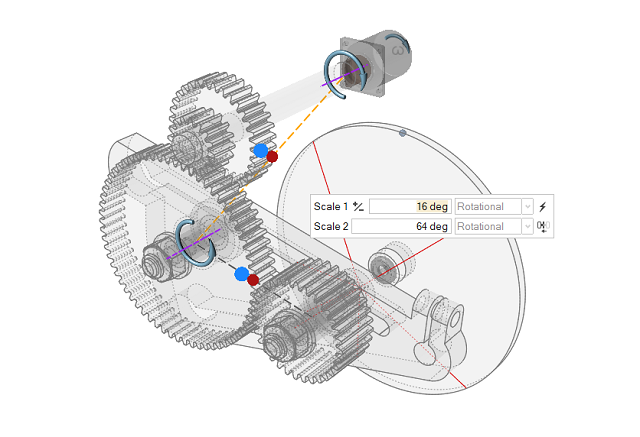
-
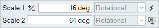
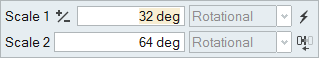
In the microdialog, note the scale factors. The software extracted the ratio
automatically from the number of teeth on the gears. This feature is only
available when you use the At Free Joints option on the guide bar.
-
Select the other coupler with the 32:64 gear ratio in the modeling window or
Model Browser and note the scale factors.
Run a Second Motion Analysis with the Joint Couplers
-
Click the Quick Run button on the Analyze Motion
tool.
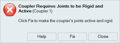
A warning message is displayed, noting that couplers require joints to be rigid and active.
-
Click the Fix button to make the couplers' joints rigid
and active.
Note: To avoid getting this error message, click the
 icon on the Couplers guide bar and select Force coupled joints
to be rigid.
icon on the Couplers guide bar and select Force coupled joints
to be rigid. -
Click the Quick Run button again to see the model in
motion, and let it run to completion.
-
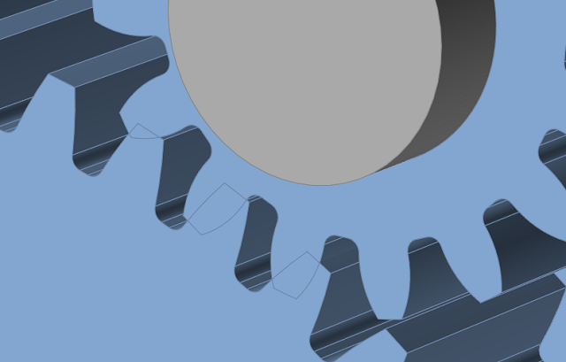
Animate the model and observe that the gear teeth on the Tumbler Gear and the
64t Gear 3/8" are passing through each other, which is incorrect. We will fix
this by reversing the direction of the joint coupler.
Reverse the Direction of Joint Coupler Motion
-
Select the Couplers tool.
-
Select the coupler that joins the Tumbler Gear and the 64t Gear 3/8" in the
modeling window or Model Browser.
The couplers are represented by pairs of blue and red circles.
-
On the microdialog, click the
 icon to reverse
the direction of joint coupler motion.
icon to reverse
the direction of joint coupler motion.
Run a Third Motion Analysis and Plot the Results
-
Click the Quick Run button on the Analyze Motion tool to
see the model in motion, and let it run to completion.
Now the gear teeth are meshing as intended.

-
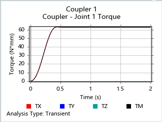
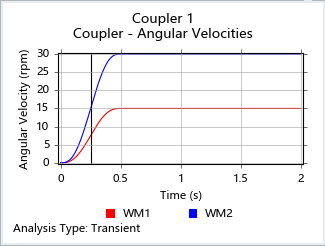
Select Coupler 1 in the Model Browser to plot the
results.
By default, the plot shows the torque in one of the coupled joints. Next we will compare the rotational speed of both joints used in the coupler.
-
Right-click on the plot and select Angular Velocities
from the context menu.
From this plot, you can see the speed ratio is 2:1.
-
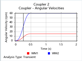
Select Coupler 2 in the Model Browser.
Now we see the ratio for Coupler 2, which is 4:1.
-
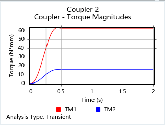
Right-click on the plot and select Torque
Magnitudes.
Torque magnitudes also exhibit the coupler ratio.