Design Spaces for Optimization
A design space is the initial geometry that forms the boundary of the optimized shape. It is typically a simplified representation of the existing part, with holes and pockets removed. Increasing the material available in the design space will yield a more optimized result.
You can create a design space by using the modeling tools in Inspire or by importing parts from other solid modelers, and then designating the relevant parts as a design space using the right-click context menu or the Property Editor
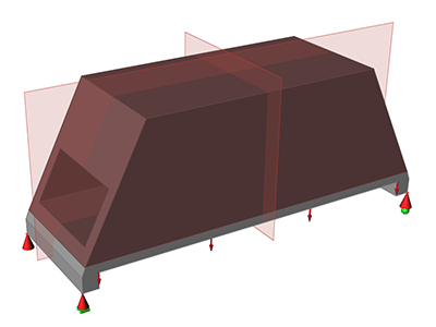
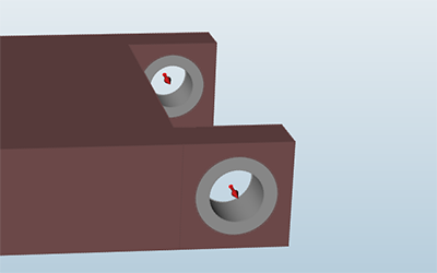
Figure 1. Design Space
A design space can be defined by any solid or surface. A part that is used as a design space should not be very detailed. To ensure the most freedom to generate a shape, you should use the simplest design space possible. The more fine details you have in the design space, the longer it will take to run the optimization.
Designate Design Space
Designate a part as a design space using the right-click context menu.
Design Space Examples
Examples of design spaces for topology and topography optimization.
Design Spaces for Topology Optimization
In topology optimization, a design space is the initial part from which material is removed until a final shape is reached during optimization.
A shape generated by optimization is contained entirely within the volume of the original design space, since material is only removed and not added. You specify the amount of material to keep either as a percentage of the design space or by entering a target weight. In the figure below, the transparent outer volume is the initial part (the design space) and the internal bridge-like structure is the shape generated using optimization.
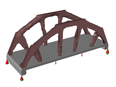 Figure 2. Bridge Design Space
Design Spaces for Topography Optimization
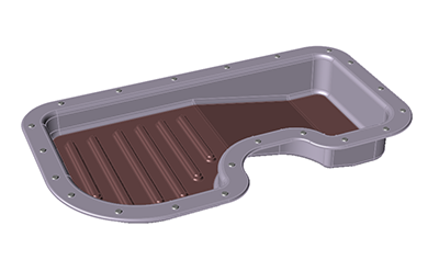
Figure 3. Oil Pan Design Space
Design and Non-Design Spaces
An important part of preparing your model for optimization is creating both design and non-design spaces.
In general, it is best not to apply loads and supports directly to design spaces, as this often leads to incorrect results. Instead, you should split the part into design and non-design spaces and apply loads and supports to the non-design spaces. When using the Push/Pull and Revolve tools, you can quickly extrude a new part to use as a non-design space by holding down the Ctrl key as you click and drag. The Partition and Boolean tools are also useful for creating non-design spaces.