Tracers
Use the Tracers tool to visualize the path of a trace point during a motion run.
After a path is drawn, it can be used for geometry creation and modification. You can synthesize shapes (like cams) from the part's motion by choosing to draw the path on a moving reference frame.
Location: Motion ribbon, Run group

Click the satellite ![]() icon that appears when you hover over the Tracers tool to
view a list of all tracers in your model.
icon that appears when you hover over the Tracers tool to
view a list of all tracers in your model.
Create and View a Tracer
-
Select the Tracers tool.
- Select a trace point to act as the pen.
- Optional: Hold the Ctrl key to select a reference point to act as the paper.
- Run the motion analysis, or if a run already exists, the trace path will appear.
- Optional: To see a partial trace path of the last ten frames during animation, select Enable Trail in the Property Editor. Adjust the trail Frames value to lengthen or shorten the trace path.
- Optional: To see a full trace path for the last valid motion run, enter the Tracers tool or use the Review Motion Results tool and view the last step in the animation.
- Right-click and mouse through the check mark to exit, or double-right-click.
Tip:
- If you move tracers with the Move tool on the microdialog, the traced paths will update automatically.
- Tracers are associated with part features. The tracer may be deleted if changes are made to the part feature or geometry associated with it.
- Tracers can be hidden or shown by clicking their icons in the Model browser or by using the context menu.
- You can change the color and line thickness of the tracer and its trace path in the Property Editor.
- The Export Locations option in the context menu allows you to save a .csv file containing global x, y, z location data.
- You can Suppress/Unsuppress a tracer to understand its effect on your model. Right-click it and select Suppress. Right-click it from the Model Browser or Table and select Unsuppress.
Creating Geometry from a Trace Path
- Create a tracer and run a motion analysis.
- Right-click on the tracer and select Create Spline from the context menu. A massless part is created in the Model Browser. This part can now be pushed, pulled, and otherwise manipulated.
Note:
- To create valid splines, make sure the trace path does not loop back over itself. Try reducing the End Time to control how far the trace path extends.
- Alternatively, you can create a polyline by selecting Create Polyline from the context menu. Polylines are segmented rather than smooth line spline curves.
- Multiple selection is supported if you have multiple trace paths that you want to convert to splines or polylines.
- If you want to keep a tracer for future use, ground the spline that you created or add it to a rigid group.
Tracers Table
The Tracers Table lists all of the tracers in your model and allows you to edit various attributes.
Location: Tracers tool, satellite icon ![]()
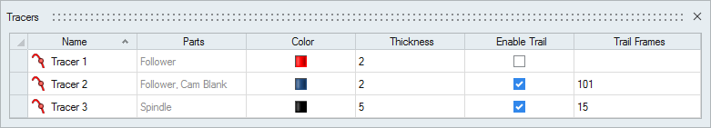
Figure 1. Tracers Table
| To | Do this |
|---|---|
| Rename a tracer | Select the cell in the table and then click again to make the field editable. |
| Change the color | Select the color cell in the table and then select a different option from the color palette. |
| Sort a column | Click the column header. Click repeatedly to toggle between ascending and descending order. |
| Add or remove columns | Right-click on a column header. |
Shortcuts
| To | Do this |
|---|---|
| Select a reference part | While a tracer is selected, hold down the Ctrl key and left-click a part to act as the paper. |
| Exit the tool | Right-click and mouse through the check mark to exit, or double-right-click. |