Joint Types and States
Every joint has a type, such as pin or hinge, and state, which can be set to locked, active, or free.
Double-click a joint to open a microdialog and edit the type or state.
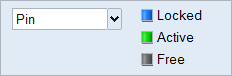
Figure 1. Joints Microdialog
Joint Types
Joints are available in a variety of types such as Pin, Hinge, or Ball and Socket. The types available vary based on the feature where the joint is being applied.
The Auto Joint Type in the table below is the type of joint that will be created if you select Auto on the Joints guide bar. If this option is selected, the tool will automatically determine the best type of joint to place at each selected (red) feature location.
| Feature | Auto Joint Type | Available Joint Types |
|---|---|---|
| Aligned holes | Pin | Pin, Grounded Pin, Sliding Pin, Grounded Sliding Pin, Ball and Socket |
| Single holes | Grounded Pin | Grounded Pin, Grounded Sliding Pin |
| Cylindrical pairs | Cylindrical | Hinge, Cylindrical, Translational, Ball and Socket |
| Cylindrical pairs + | Hinge | Hinge, Cylindrical, Translational, Ball and Socket, Planar |
| Spherical pairs | Ball and Socket | Ball and Socket |
| Planar pairs | Planar | Planar |
| Multi-planar pairs | Translational | Translational, Cylindrical |
When a joint isn't recognized as any of the above types, it is categorized as an Unknown joint.
| Available Joint Types | Translational DOF* | Rotational DOF |
|---|---|---|
| Hinge, Pin, Grounded Pin | 0 | 1 |
| Cylindrical, Sliding Pin, Grounded Sliding Pin | 1 | 1 |
| Translational | 1 | 0 |
| Planar | 2 | 1 |
| Ball and Socket | 0 | 3 |
*DOF = Degrees of freedom of idealized (rigid) joint.
- Grounded pins and grounded sliding pins act as supports in load cases. They mimic the pin being fastened to another part that is not available in the model. The axial and shear stiffness of grounded joints can be modified in the Property Editor.
- The Ball and Socket type is included for aligned holes, single holes, and cylindrical pairs for debugging purposes. If the motion of the system is locked up, you can change a pin into ball and socket to see if the system starts to move.
- There are situations where the software cannot recognize a suitable type of joint for some geometry features, in which case the type is defined as Unknown.
- The cylindrical pairs + designation is only viewable in the Joints table.
Joint States
Each joint has a state which can be set to Locked, Active, or Free.
| Options | Description |
|---|---|
| Locked | Prevents movement in the joint. This is useful for debugging and what-if scenarios. |
| Active | Allows the joint to function normally. |
| Free | The mechanism will behave as if the joint is not there. |
- By default, all joints are set to Active unless their type is Unknown, in which case they are set to Free. If an Unknown joint is set to Active, its type will be automatically redefined as Ball and Socket.
- You can Suppress/Unsuppress a joint to understand its effect on your model. Right-click it and select Suppress. Right-click it from the Model Browser or Table and select Unsuppress.
Joint Type Examples
Following are examples of detected features shown with the typical best joint type.
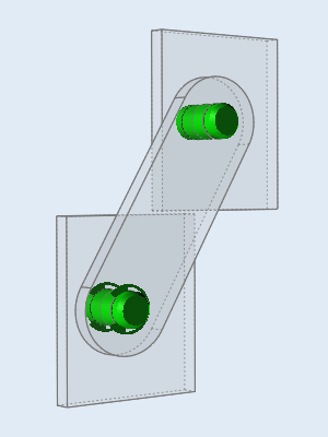
Figure 2. A pin and sliding pin placed at aligned holes
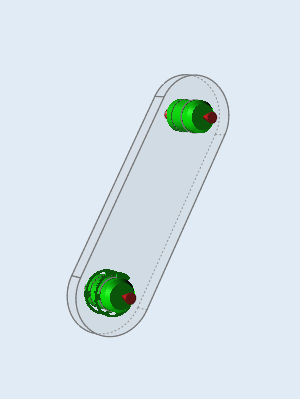 Figure 3. A grounded pin and grounded sliding pin placed at single holes
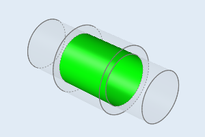
Figure 4. A cylindrical joint placed at a cylindrical pair
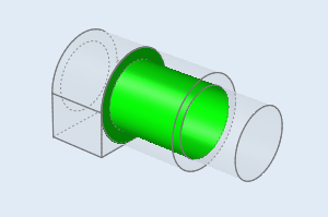
Figure 5. A hinge joint placed at a cylindrical pair plus
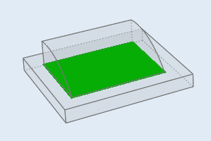
Figure 6. A planar joint placed at a planar pair
Figure 7. A translational joint placed at a multi-planar pair
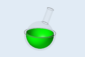
Figure 8. A ball and socket joint placed at a spherical pair