Materials
The different material types provided by OptiStruct are: isotropic, orthotropic, and anisotropic materials. The material property definition cards are used to define the properties for each of the materials used in a structural model.
The MAT1 Bulk Data Entry is used to define the properties for isotropic elastic materials. It can be referenced by any of the structural elements and can also be referenced by any property card.
The MAT2 entry is used to define the properties for anisotropic materials. It applies only to triangular or quadrilateral membrane and bending elements, and can only be referenced by PSHELL, PCOMP, and PCOMPG property cards. This material type specifies the relationship between the in-plane stresses and strains. The angle between the material coordinate system and the element coordinate system is specified on the connection cards.
The MAT3 entry is used to define the material properties for axisymmetric and plane-strain elements. It can be referenced by CTRIAX6 elements and can also be referenced by any PAXI property card which is in turn referenced on CTAXI or CQAXI elements. Similarly, it can be referenced by the PPLANE property which is referenced by plane-strain CQPSTN and CTPSTN elements.
The MAT4 entry is used to define the isotropic thermal material properties. It can be referenced by any of the structural elements, and can also be referenced by any property card.
The MAT5 entry is used to define the anisotropic thermal material properties. It can be referenced by any of the structural elements and can also be referenced by any property card.
The MAT8 card is used to define the properties for planar orthotropic elastic materials in two dimensions. Individual plys of a layered composite lay-up typically possess such orthotropic properties. Since layered composite laminates are modeled using shell elements, MAT8 property data can only be referenced by PSHELL, PCOMP, and PCOMPG property cards.
The MAT9 Bulk Data Entry can be used to define the properties for anisotropic elastic materials for three dimensional solid elements. The general an-isotropic stress-strain relationship linking the six independent stress components of the stress tensor at a point and the six independent strain components of the tensor at the point contain 21 independent constants in the elasticity matrix. These values are supplied using the MAT9 Bulk Data card. The MAT9 Bulk Data card is used with the CHEXA, CPENTA, CPYRA, and CTETRA solid elements, and can only be referenced on the PSOLID property card. The optional coordinate system in which MAT9 data are specified is supplied via the PSOLID Bulk Data Entry.
The MAT10 Bulk Data Entry is used to define material properties for fluid elements in coupled fluid-structural (acoustic) analysis. It may only be referenced on PSOLID entries with FCTN=PFLUID.
Biot (poroelastic) material is defined using MATPE1 entry.
Temperature dependent material properties are defined using MATT1, MATT2, MATT8, and MATT9. All four have the same characteristics as described above. The temperature dependency of each property is defined through TABLEM1, TABLEM2, TABLEM3, or TABLEM4 table entries.
Composite Laminates are defined using the PCOMP, PCOMPP and PCOMPG properties. They are not material types; each ply in the laminate lay-up can reference a different material.
Elasto-plastic material properties are defined using MATS1. The nonlinear material characteristics may need the table input TABLES1. MATS1 is defined as an extension to a MAT1 with the same MID. MATS1 is applicable to all nonlinear solutions.
Hyperelastic material properties are defined using MATHE. Various Hyperelastic material models are available, such are Ogden, Arruda-Boyce, and so on.
Viscoelastic material properties are defined using MATVE or MATFVE, if frequency-dependency is required.
Creep material properties are defined using MATVP.
Cohesive Zone Modeling can be defined using MCOHE or MCOHED entries.
Cast Iron Plasticity material can be defined using MCIRON Bulk Data Entry.
User-defined structural material properties are available using MATUSR. .dll or .so libraries can be referenced via the LOADLIB entry. For more information, refer to User-Defined Structural Material in the User Guide.
User-defined thermal material properties are available using MATUSHT. .dll or .so libraries can be referenced via the LOADLIB entry.
Material models can also be defined using Multiscale Designer and used via the MATMDS entry.
| Material Property | Nonlinearity | Time-dependency | Temperature-dependency | Frequency-dependency | Material Card |
|---|---|---|---|---|---|
| Isotropic | - | - | - | - | MAT1 |
| - | - | - | Yes | MAT1 + MATF1 | |
| - | - | Yes | - | MAT1 + MATT1 | |
| Elasto-plasticity | - | - | - | MAT1 + MATS1 | |
| Elasto-plasticity | - | Yes | - | MAT1 + MATS1 (referencing TABLEST) | |
| Hyperelasticity | - | - | - | MATHE | |
| Viscoelasticity | - | - | - | MAT1 + MATVE | |
| Viscoelasticity | - | - | Yes | MAT1 + MATFVE | |
| Viscoelasticity, Hyperelasticity | - | - | - | MATHE + MATVE | |
| Creep | - | - | - | MAT1 + MATVP | |
| Creep, Elasto-plasticity | - | - | - | MAT1 + MATVP + MATS1 | |
| Creep | - | Yes | - | MAT1 + MATVP + MATTVP | |
| Anisotropic | - | - | - | - | MAT9 (solid
elements) MAT2 (shell elements) |
| - | - | - | Yes | MAT9 + MATF9 (solid
elements) MAT2 + MATF2 (shell elements) |
|
| - | - | Yes | - | MAT9 + MATT9 (solid
elements) MAT2 + MATT2 (shell elements) |
|
| Viscoelasticity | - | - | - | MAT9 + MATVE | |
| Viscoelasticity | - | - | Yes | MAT9 + MATFVE | |
| Orthotropic | - | - | - | - | MAT9OR (solid
elements) MAT8 (shell elements) MAT3 (axisymmetric and plane strain elements) |
| - | - | - | Yes | MAT8 + MATF8 (shell
elements) MAT3 + MATF3 (axisymmetric and plane strain elements) |
|
| - | - | Yes | - | MAT9OR + MATT9OR (solid
elements) MAT8 + MATT8 (shell elements) MAT3 + MATT3 (axisymmetric and plane strain elements) |
|
| Fluid | - | - | - | - | MAT10 |
| - | - | - | Yes | MAT10 + MATF10 | |
| Thermal | - | - | - | - | MAT4 (Isotropic) MAT5 (Anisotropic) |
| Yes (Temperature) | - | Yes | - | MAT4 + MATT4 (Isotropic) | |
| Gasket | - | - | Yes | - | MGASK |
| Fatigue | - | - | - | - | MATFAT |
| Biot (Poroelasticity) | - | - | - | - | MATPE1 |
| User-Defined Structural Material Subroutines | Yes | Yes | Yes | - | MATUSR (Fortran and C for subroutines) |
| User-Defined Thermal Material Subroutines | Yes (Temperature) | Yes | Yes | - | MATUSHT (Fortran and C for subroutines) |
| Multiscale Designer-based Material | Yes | - | - | - | MATMDS (using Altair Multiscale Designer). |
| Failure Criteria | - | - | - | - | Criteria and Allowables on
MATF Criteria/Allowables can also be defined on MAT1, MAT2, MAT8, PCOMP, PCOMPP, PCOMPG |
| Material Property | Nonlinearity | Time-dependency | Temperature-dependency | Frequency-dependency | Material Card |
|---|---|---|---|---|---|
| Isotropic | - | - | - | - | MAT1 |
| Elasto-plasticity | - | - | - | MAT1 + MATS1 | |
| Hyperelasticity | - | - | - | MATHE | |
| Viscoelasticity | - | - | - | MAT1 + MATVE | |
| Viscoelasticity, Hyperelasticity | - | - | - | MATHE + MATVE | |
| Anisotropic | - | - | - | - | MAT2 (shell elements) |
| Viscoelasticity | - | - | - | MAT9 + MATVE | |
| Orthotropic | - | - | - | - | MAT8 (shell elements) |
For explicit dynamic subcases (with Radioss integration), more nonlinear material laws are available. As a general rule, material definitions that are only applicable in explicit dynamic analysis are defined on extensions to a MAT1 material that defines the basic elastic properties. The extensions are grouped with the base entry by sharing the same MID. The MATXyz extensions available are listed below. If a law requires material curves, TABLES1 entries are used.
Explicit Dynamic Analysis (Radioss Integration via ANALYSIS=EXPDYN)
- Material Card
- Description
- MATX0
- Void material
- MATX02
- Johnson-Cook elastic-plastic material
- MATX13
- Rigid material
- MATX21
- Rock-Concrete material
- MATX25
- Composite shell material, TSAI-WU and CRASURV formulations
- MATX27
- Brittle elastic-plastic material
- MATX28
- Honeycomb material
- MATX33
- Visco-elastic foam material
- MATX36
- Piece-wise linear elastic-plastic material
- MATX42
- Ogden-Mooney and Rivlin material
- MATX43
- Hill orthotropic material
- MATX44
- Cowper-Symonds elastic-plastic material
- MATX60
- Piece-wise nonlinear elastic-plastic material
- MATX62
- Hyper-visco-elastic material
- MATX65
- Tabulated strain-rate dependent elastic-plastic material
- MATX68
- Honeycomb material
- MATX70
- Tabulated visco-elastic foam material
- MATX82
- Ogden material
User-Defined Structural Material
The MATUSR Bulk Data Entry, in combination with the LOADLIB I/O Option Entry, allows for the definition of structural material through user-defined external functions.
The external functions may be written in Fortran or C. The resulting libraries and files should be accessible by OptiStruct regardless of the coding language, provided that consistent function prototyping is respected, and adequate compiling and linking options are used.
Write External Functions
The OptiStruct installation provides an example file with subroutines for Fortran (umat.F) with proper subroutine definition, arguments, and compilation directives. This file can be used as a starting point to write your own subroutines. This file is located at $ALTAIR_HOME/hwsolvers/demos/optistruct.
Two Fortran subroutines are required to define user material in OptiStruct. First, a Nonlinear subroutine for the nonlinear solution, and another subroutine for the linear solution. Both subroutines are mandatory, and the same argument order should be followed as:
subroutine usermaterial(idu, stress, strain, dstrain, stater,
 state, nstate, drot, props, nprops,
 temp, dtemp, ieuid, kinc, dt, t_step,
 t_total, cdev, cbulk)

integer idu, nstate, nprops, kinc, ieuid
double precision stress(6),stater(*),state(*),
     $     cdev(6,6),cbulk, drot(3,3), temp, dtemp, dt,
     $     t_step, t_total,
$ strain(6), dstrain(6), props(nprops)subroutine smatusr(idu, nprop, prop, smat)
integer idu, nprop
double precision prop(nprop), smat(*)Subroutine Arguments
| Argument | Type | Input / Output | Description |
|---|---|---|---|
idu |
integer | Input | This is defined via the USUBID parameter
on the MATUSR Bulk Data Entry. This argument
can be used to define and choose between different types of
materials within the same user subroutine. optional use |
stress |
double (table) | Input/Output | This is the Stress tensor. The initial stress is considered to be input and the stress, tensor calculated during the nonlinear solution are output from the user subroutine to OptiStruct. |
strain |
double (table) | Input | Strain tensor. The initial strain is considered to be input. |
dstrain |
double (table) | Input | Incremental strain table. The incremental strain is input from OptiStruct to the user subroutine. |
stater |
double (table) | Input/Output | Table of State variables at the previous increment. State variables are variables that can be requested as output in the H3D file. Any variable (for example, plastic strain, equivalent plastic strain, and so on) calculated within the solution process in the subroutine can be output by defining it as a state variable. |
state |
double (table) | Input/Output | Table of State variables at the current increment. See
stater for more information. |
nstate |
integer | Input/Output | Number of State Variables that the user requires in the
subroutine. See stater for more information.
|
props |
double (table) | Input | This table contains all the user-defined material property information from the PROPERTY continuation line of the MATUSR entry. |
nprops |
Integer | Input | This is the total number of material properties defined on the PROPERTY continuation line of the MATUSR entry. |
temp |
double | Input | This is the temperature at the previous converged increment. |
dtemp |
double | Input | This is the temperature increment. |
ieuid |
integer | Input | Element ID. This subroutine is called for every integration point for every element. |
kinc |
integer | Input | Current increment. |
dt |
double | Input | Current Time increment |
t_step |
double | Input | Subcase time. |
t_total |
double | Input | Total time (if CNTNLSUB is used) |
cdev |
double (table) | Output | Deviatoric material modulus matrix. These are calculated during the solution and are output to OptiStruct to form the stiffness matrix. |
cbulk |
double (table) | Output | Bulk material modulus Matrix. These are calculated during the solution and are output to OptiStruct to form the stiffness matrix. |
smat |
Double (table) | Output | Material modulus matrix. These are calculated during the solution and are output to OptiStruct to form the stiffness matrix. |
Build External Libraries for User-defined Materials
Allows building shared libraries on Windows or Linux.
Refer to Build External Libraries for more information.
User-Defined Thermal Material
The MATUSHT Bulk Data Entry, in combination with the LOADLIB I/O Option Entry, allows for the definition of thermal material through user-defined external functions.
The external functions may be written in Fortran or C. The resulting libraries and files should be accessible by OptiStruct regardless of the coding language, provided that consistent function prototyping is respected, and adequate compiling and linking options are used.
Write External Functions
The OptiStruct installation provides an example file with subroutines for Fortran (userlmat.F) with proper subroutine definition, arguments, and compilation directives. This file can be used as a starting point to write your own subroutines. It is located at $ALTAIR_HOME/hwsolvers/demos/optistruct.
subroutine usrmatht(idu, matID, ieuid, Stater, State,
 nState, drot, rmat, nprops, etempmat,
 dtemp, kinc, dt, t_step, hgen, smat)

integer*8 i, idu, matID, ieuid, nState, nprops, kinc
      double precision Stater(nState), State(nState)
      double precision drot(3,3), rmat(nprops)
      double precision etempmat, dtemp, dt, t_step
      double precision hgen, smat(*)
Subroutine Arguments
| Argument | Type | Input / Output | Description |
|---|---|---|---|
idu |
integer | Input | This is defined via the USUBID parameter
on the MATUSHT Bulk Data Entry. This argument
can be used to define and choose between different types of
materials within the same user subroutine. optional use |
matID |
Integer | Input | Material ID. |
ieuid |
integer | Input | Element ID. This subroutine is called for every integration point for every element. |
drot(3,3) |
Double (table) | Input | Transformation matrix. |
props |
double (table) | Input | This table contains all the user-defined thermal material property information from the PROPERTY continuation line of the MATUSHT entry. |
nprops |
Integer | Input | This is the total number of thermal material properties defined on the PROPERTY continuation line of the MATUSHT entry. |
temp |
double | Input | This is the temperature at the end of the current increment. |
dtemp |
double | Input | This is the temperature increment of the current increment. |
kinc |
integer | Input | Current nonlinear increment. |
dt |
double | Input | Current time step increment |
t_step |
double | Input | Current subcase time of the current time step. |
Stater |
double (table) | Input/Output | Table of State variables at the last converged time-step. They are constant between iterations of the same time step. State variables are variables that can be requested as output in the H3D file. Any variable calculated within the solution process in the subroutine can be output by defining it as a state variable. |
State |
double (table) | Input/Output | Table of State variables at the current time-step. They are
updated and passed between iterations of the same time-step. See
Stater for more information. |
nState |
integer | Input/Output | Number of State Variables that the user requires in the
subroutine. See Stater for more
information. |
hgen |
double (table) | Output | Generated heat at the integration point. |
smat |
Double (table) | Output | Material matrix. These are calculated during the solution and
are output to OptiStruct. Format for
smat matrix is provided below.
|
Build External Libraries for User-defined Materials
You can build shared libraries on Windows or Linux.
Refer to Build External Libraries for more information.
Cast Iron Plasticity
Cast iron material model is used to describe the yield behavior of grey cast iron, in which tension and compression behavior are different.
- is the tensor form of deviatoric stress.
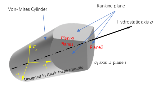
Figure 1.
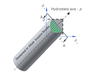
Figure 2.
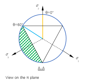
Figure 3.
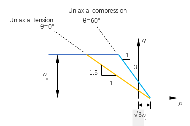
Figure 4.
Hardening Rule
In this material model, only isotropic hardening is considered. The yield strength is increasing as the equivalent plastic strain grows. It is noted that as tension and the compression have different flow rules, the equivalent plastic strain is different for tension and compression. Hence, the tensile yield strength and the compressive yield strength are looked up from the tensile and the compressive table separately.
Where, is the tensor of deviatoric part of plastic strain rate.
Where, .
In the above expressions, the subscript index implies the physical quantity is at time , and means the physical quantity is at the last converged time .
Input
Cast iron plasticity material data can be specified by using the MCIRON Bulk Data Entry which has the same identification number as an existing MAT1 Bulk Data Entry. The Tensile and Compressive stress-strain curves can be defined using the TABLE_T and TABLE_C fields on the MCIRON entry.
Cast iron material via MCIRON is supported for Small and Large Displacement Nonlinear Static Analysis. It is supported for CHEXA, CTETRA, CPENTA, and CPYRA elements (both first and second order).
In addition to regular result output, additional results from this material model are output if STRAIN(PLASTIC) I/O Option is specified. These results include, 6 plastic strain components, equivalent compressive plastic strain, equivalent tensile plastic strain, nodal results, and integration results are also available.
Multiscale Modeling
OptiStruct (OS) and Multiscale Designer (MDS) can be combined to perform multiscaling analysis on structural components utilizing both linear and nonlinear materials.
Heterogeneous materials such as composites, soil, solid foams, and polycrystals consist of one or more distinguishable constituents that have different mechanical properties. 3 For example, it is known that fiber-reinforced composite materials have a stiffer and stronger phase known as the reinforcement and, a less stiff and weaker phase known as the matrix. The governing equations are well understood in one of the scales, either the micro-scale or the macro-scale. While general constitutive equations are applicable to solids under deformation in the macro-scale, continuum models are required in the micro-scale. In order to bridge the gap between the two scales, you need to consider models at different scales simultaneously. This can be achieved by multiscaling techniques.
Classical laminate theory can predict the overall properties of heterogeneous laminates; whereas, homogenization theory provides information on the individual phase properties and phase geometries. Knowledge of individual phases is important to characterize material damage and failure. Hence, multiscaling techniques open unique opportunities for modeling by focusing the material behavior on different levels of physical laws.

Figure 5. Multiscale Designer - OptiStruct Integration
- Unit cell geometry and mesh definition
- Linear material characterization
- Reduced-order homogenization
- Nonlinear material characterization
Single-scale Model
The basic steps required to construct a single-scale material model.
Cast iron plasticity is interesting to study because it has different yielding and hardening behavior when subjected to tensile and compressive loads. The first two sections explain the input data required from the Multiscale Designer (MDS). The next two sections explain the procedure to integrate the material in OptiStruct (OS) and perform structural analysis.
Linear Material Characterization
- isotropic
- trans-isotopic
- orthotropic
- anisotropic material
Here a homogeneous material with the properties of cast iron is utilized for characterization in the linear regime. The input elastic properties/parameters and values of the material are:
- Tensile Young’s modulus (GPa),
- 95.5
- Compressive Young’s modulus (GPa),
- 95.5
- Poisson's ratio,
- 0.26
Nonlinear Material Characterization
Various constitutive laws are available in Multiscale Designer, such as rate-independent plasticity, visco-elasticity, damage laws. Here isotropic damage – 3-piecewise Linear Evolution is used to simulate the nonlinear behavior of the material. The damage model formulation within Multiscale Designer follows the continuum damage mechanics framework. The elastic stiffness matrix is degraded by using a damage state variable which is a function of principal strains. Only for compressive loads, the principal strains are multiplied by a compression factor to alleviate the damage in compression. The compression factor is calculated internally, based on the input properties of the material.
- Stress at damage initiation – tension (MPa),
- 126.0
- Ultimate stress – tension (MPa),
- 210.3
- Strain at ultimate stress - tension,
- 0.008
- Strain to failure – tension,
- 0.008
- Stress at damage initiation – compression (MPa),
- 303.0
- Ultimate stress - compression (MPa),
- 443.3
- Strain at ultimate stress - compression,
- 0.010
- Strain to failure – compression,
- 0.010
Nonlinear material characterization is done with a Unnotched Tensile/Compression built-in macro simulation model. Two simulations are defined conforming to ASTM D3039, D3518 and D6641. One to simulate tensile behavior and one for compressive behavior. In the process, a unit mesh – solid cube is fixed on one end and subjected to x-direction displacement on the other end. The stresses are computed by extracting, the reaction forces divided by unit area.
- Loading rate – Tension (/s)
- 0.008
- Maximum strain - Tension
- 0.008
- Loading rate – Compression (/s)
- -0.01
- Maximum strain - Compression
- -0.01
The loading rate is the strain rate for the test. For all-rate independent laws (this includes isotropic damage law – 3 piecewise Linear evolution), it is typical to set the loading rate equal to the maximum strain. The minimum number of increments for mechanical loads is defined to be 20. This means that the initial time-step is set as the total step time divided by minimum mechanical increments.
The output data files are generated in the material model directory. The file path can be changed in the Multiscale Designer settings. The corresponding file names and descriptions are availble in ‘Unit Cell Data Files’ of the Multiscale Designer User Manual.
Structural Analysis
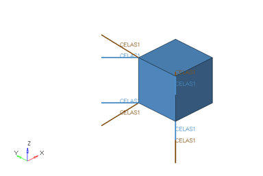
Figure 6. Unit CHEXA Cube Element Model Connected to Springs
Integrate Multiscale Designer Files with OptiStruct
Single-scale Results
Sample cards are generated for Multiscale Designer-OptiStruct integration, with the results of tension and compression test in OptiStruct with the user-defined material.
Elastic properties from homogenization and stress-strain curve from damage law are presented.
Linear Material Characterization
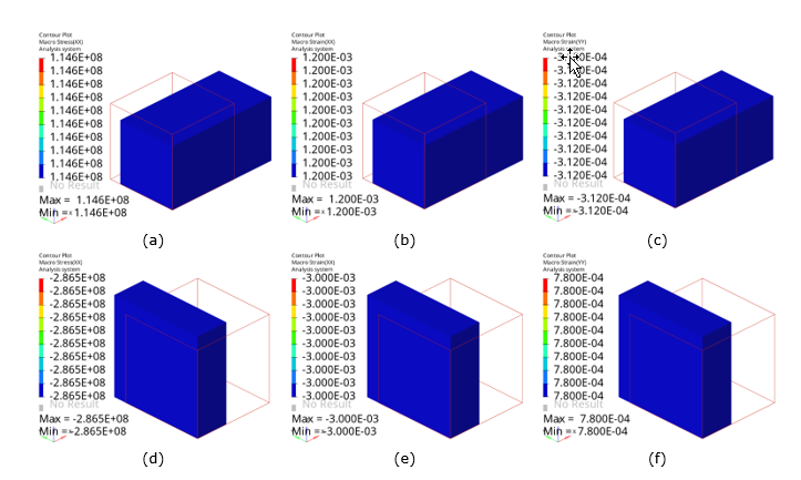
Figure 7. Built-in Macro Simulation in Multiscale Designer (Contour Plots). (a) and (d) x-direction stress in tension and compression, respectively; (b) and (e) x-direction strains in tension and compression, respectively; and (c) and (f) y-direction strains in tension and compression, respectively
- Tensile Young’s modulus (GPa),
- 95.5
- Compressive Young’s modulus (GPa),
- 95.5
- Poisson's value,
- 0.26
Nonlinear Material Characterization
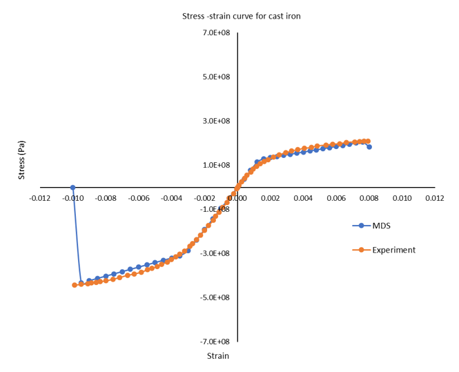
Figure 8. Stress-Strain Curve of Cast Iron from Multiscale Designer and Experiment
Multiscale Designer-OptiStruct Integration

Figure 9. OptiStruct Plugin File from Multiscale Designer
Structural Analysis
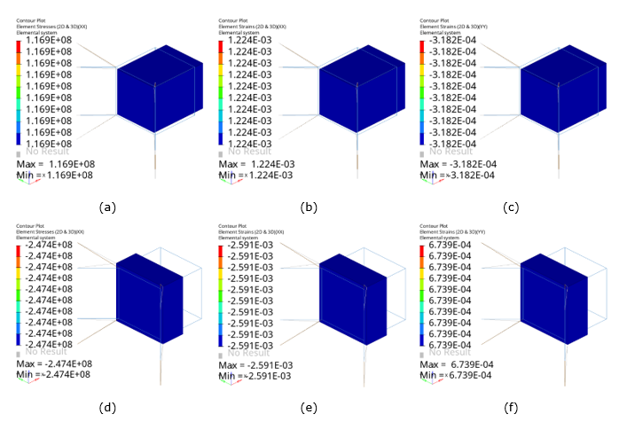
Figure 10. Structural Analysis in OptiStruct (Contour Plots). (a) and (d) x-direction stress in tension and compression, respectively; (b) and (e) x-direction strains in tension and compression, respectively; and (c) and (f) y-direction strains in tension and compression, respectively
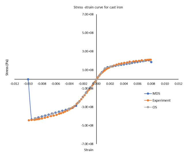
Figure 11. Stress-Strain Curve of Cast Iron
Multiscale Model
The basic steps required to construct a multiscale material model.
Unidirectional fiber-reinforced polymer composite is subjected to tensile load in fiber-axial and fiber-transverse directions. The response of the material is output and validated with experimental data. The first two sections explain the input data required from the Multiscale Designer (MDS). The next two sections explain the procedure to integrate the material in OptiStruct (OS).
Unit Cell Model and Linear Material Characterization
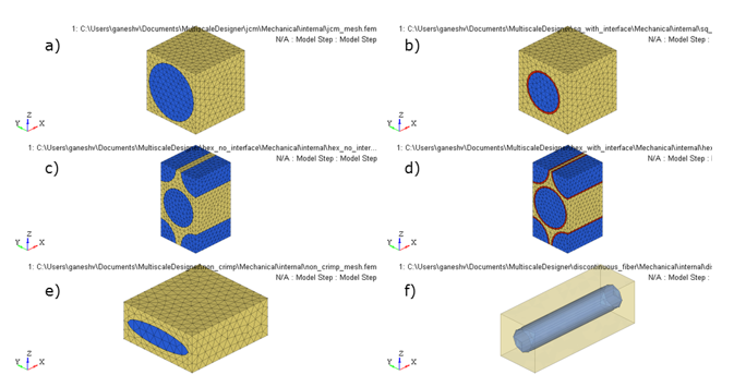
Figure 12. Fibrous Unit Cell Models. (a) square packing array; (b) square packing array with an interface; (c) hexagonal packing array; (d) hexagonal packing array with interface; (e) non-crimp ellipsoidal fabric; and (f) discontinuous fiber packing array
The matrix is modeled with homogeneous elastic properties and the fiber is assumed to be transversely isotropic. Periodic boundary conditions are applied to the unit cell to obtain the homogenized stiffness matrix of the composite.
- Young’s modulus of the matrix (GPa),
- 3.8
- Poisson’s ratio of the matrix,
- 0.32
- Longitudinal Young’s modulus of fiber (GPa),
- 252.25
- Transverse Young’s modulus of fiber (GPa),
- 13.45
- Longitudinal Poisson’s ratio,
- 0.02
- Transverse Poisson’s ratio,
- 0.3
Nonlinear Material Characterization
The matrix is assumed to obey isotropic damage – bilinear evolution model and the fiber is assumed to follow orthotropic damage – bilinear evolution, for simulating the nonlinear behavior of the material.
- Stress at damage initiation (MPa),
- 126.0
- Strain at ultimate stress,
- 0.1
- Stress at damage initiation – longitudinal direction (GPa),
- 4.2
- Strain at ultimate stress – longitudinal direction,
- 0.017
- Stress at damage initiation – transverse direction (MPa),
- 75.0
- Strain at ultimate stress – transverse direction,
- 0.05
For nonlinear material characterization in fiber-axial and fiber-transverse direction, two laminate layups with unit thickness are created with orientations 0° and 90°, respectively. Each laminate is subjected to Unnotched Tensile/Compression macro simulation with different loading rates.
- Loading rate – Fiber axial direction test (/s)
- 0.05
- Maximum strain - Fiber axial direction test
- 0.05
- Loading rate – Fiber transverse direction test (/s)
- 0.017
- Maximum strain - Fiber transverse direction test
- 0.017
The output data files are generated in the material model directory and the stress-strain curve data will export to an Excel spreadsheet file in <material_model_directory\model_name\mechanical\model_name_NLmatl.xlsx>.
Integrate Multiscale Designer Files with Multiscale Designer-OptiStruct
Multiscale Results
Sample cards are generated for Multiscale Designer-OptiStruct integration with OptiStruct test results.
Elastic properties from homogenization and stress-strain curve from damage law are presented.
Unit Cell Model and Linear Material Characterization
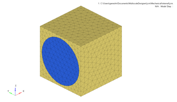
Figure 13. Unit Cell Model of Square Packing Array . with Fiber Volume Fraction = 65%
- Longitudinal Young’s modulus (GPa),
- 165.4
- Transverse Young’s modulus (GPa),
- 8.8
- Longitudinal Poisson’s ratio,
- 0.11
- Transverse Poisson’s ratio,
- 0.34
Nonlinear Material Characterization
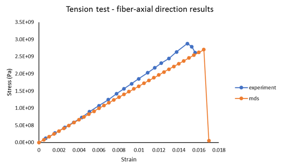
Figure 14. Comparison of Stress-Strain Curves. fiber-axial tensile test from Multiscale Designer and experiment
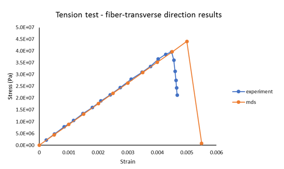
Figure 15. Stress-Strain Curve. fiber-transverse tensile test from Multiscale Designer and experiment
Multiscale Designer-OptiStruct Integration

Figure 16. Homogenized Composite Properties in OptiStruct MAT9ORT Format