|
»Click here to display Table of Contents«
|

Viewport Control Panel |

|

|

|

|
|
Viewport Control Panel |
|
|
|

|
|
»Click here to display Table of Contents«
|
Viewport Control Panel |
|
|
|
|
|
Viewport Control Panel |
|
|
|
|
This is the first icon from left on the Main Viewport. This panel provides options for selecting the type of boundary/mesh display, toggling the 3D axis on and off, selecting a light source position, setting the plot quality, and more. The functionality of each option appearing on this panel is described below.
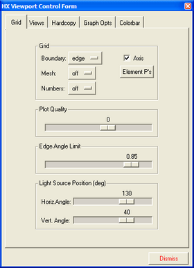
The Viewport Control panel
The first group of options on the Viewport Control panel allows you to select the type of display for the computational mesh and whether the 3D axis is on or off.
Field |
Description |
Boundary |
Sets the display mode for the boundary of the object. The display options include: no boundary display off, edges of the object edge, a wireframe view of the boundary elements or surfaces wire and opaque, shaded or transparent. |
Axis |
Toggles on/off an x, y, z triad at the bottom of the viewport. |
Mesh |
Enables you to display the mesh in various modes. Off turns the mesh display off. Full displays all element boundaries color coded by p-order. no p displays all element edges with a linear solution approximation along their directions. p>1 displays all element edges with p > 1 along their directions. p=n displays all elements edges with p =n along their directions. |
Element P's |
Displays the Crosshair Editor panel for displaying p nodes. With this option p-degrees of freedom are displayed on the element faces and at the central node. Developers for serious debugging typically use this option. |
Numbers |
Places corner node and/or element numbers on the mesh. Original corner nodes and element numbers are indicated using negative values and adapted nodes/elements are given positive values. |
The remaining sections of the Viewport Control panel set the plot quality and light source position for shading, and also provide access to additional panels for customizing the color spectrum and viewing angles for objects displayed in the Main Viewport window.
Field |
Description |
Plot Quality |
This option controls the number of element divisions (-4 < value < 3) used by the graphical tools for interpolating the solution. Thus the smoothness and the required execution time of isosurfaces greatly increases as the number of divisions is increased. The computation of isosurfaces requires a search through all unrefined elements and, for p elements, non-trivial interpolation within the elements to determine the true behavior of the surfaces. A lower number implies a coarser surface, but less time. For nonlinear elements, as well as for some nonlinear derived quantities, an insufficient number of divisions can result in discontinuities appearing between elements on a constrained edge. The actual number of subdivisions used in the display depends on the selected Plot Quality as well as the p-order of each element. As indicated above the plot quality values affect the performance and possibly the appearance of all of the post-processing options including: slices, isosurfaces, mesh/grid, etc. |
Edge Angle Limit |
Defines a relative scale for controlling the selection of which edges in the model to display for all classes of boundary plots with '+edge' in their name. This scale ranges from 0.0 to 0.99 with larger values of the scale showing smaller brake angles between element faces. For quadratic geometries, a scale value of zero provides much higher resolution of element edges. |
Light source position (deg) |
This option provides two slider bar options for controlling the position of the light source for shaded and transparent boundary plots. The Horiz. angle controls the rotation of light source about the Z-axis. Vert. angle controls the rotation about the Y-axis. The light source is positioned with respect to the X, Y, Z coordinate system, not the with respect to the screen. |
Dismiss |
Closes the panel. |
| Note: | Most of the options on the Viewport Control panel are action items that are performed immediately. The other options selected here are enforced as other graphical tools are activated. |