|
»Click here to display Table of Contents«
|

View Form |

|

|

|

|
|
View Form |
|
|
|

|
|
»Click here to display Table of Contents«
|
View Form |
|
|
|
|
|
View Form |
|
|
|
|
This panel provides options for storing and loading selected viewing positions, setting the projection type, locating the front and back clipping planes and more. The controls available here are independent of the mouse motions and operate immediately on the object displayed in the Main Viewport window.
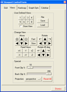
The View Form
The functionality of each of the options appearing on this panel is described below.
Field |
Description |
User Defined Views |
Stores the current view displayed in the Main Viewport window in the database. This option operates in conjunction with the buttons labeled 1, 2, 3, … to store up to eight viewing positions and window sizes. Only the viewing position is stored not the isosurfaces, slices, etc. To store a viewing position, Store view and then one of the storage buttons labeled 1, 2, 3, …. To retrieve the view later in the same session, click the corresponding numbered button. |
Save |
This is a hot button for writing a save file which contains the views stored in the view buttons labeled 1 through 8. Any acceptable file name may input here next to the File: option with the default output save file named phlex.views. The view save file is created in an overwrite mode and all of the previous views contained in a given file will be lost as subsequent Save's are made. |
Load |
This option is used to load a predefined set of views stored with the Save option. To load a given set of saved views, enter the name of the view file after File: and then click Load. This loads the saved views into the hot buttons 1,2, etc. |
Move and Rotate |
These options provide twelve hot buttons for translating, zooming in and out, and rotating the object displayed in the Main Viewport window. The rate at which the object is moved is controlled by the Fast and Slow options located in the center of the panel. The Fast and Slow buttons have four magnitude settings which vary depending on the type of motion selected. For translations the magnitudes are 1, 10, 50, and 100 percent of the smallest dimension of the viewport; for zooming in or out the magnitudes are 1.02, 1.10, 1.40, and 2.0 times; and for rotating the magnitudes are 0.1, 1, 2, and 5 degrees. The twelve buttons that perform the translations and rotations are transparent in their functionality. The + and – options are for zooming in and out respectively. The rotation of the body always occurs about a fixed coordinate system located at the center of the viewport with X to the right, Y up, and Z pointing outward. With this convention the L and R options rotate the object about the Z-axis, the up and down arrows rotate about the X-axis and the left and right arrows rotate about the Y-axis. |
Fixed views |
There are six fixed view options which may be used to place the observer along one of the X, Y, or Z coordinate axis. These options reset the object position in the center of the Main Viewport with the observer looking at the origin of the coordinate system. These fixed views do not reset the clipping planes or projection type. |
Rotate 45 deg |
These options rotate the object in 45 degree increments. The rotation of the body always occurs about a fixed coordinate system located at the center of the viewport with X to the right, Y up, and Z pointing outward. With this convention the L and R options rotate the object about the Z-axis, the up and down arrows rotate about the X-axis and the left and right arrows rotate about the Y-axis. |
Projection |
This selects perspective versus parallel (isometric) visualization of the model. |
Front Clip/Back Clip |
This option sets the position of the front clipping plane, permitting an interior examination of the model. In particular, this option sets the position of the front clipping plane as a percentage of distance to the center of the bounding box containing the model. The initial position (default location) of the front clipping plane is at ten percent of the distance to the center. As the percentage is increased, the front clipping plane is moved toward the center of the bounding box removing portions of the model between the clipping plane and the viewer. When the percentage reaches 100 percent the front clipping plane will be located at the center of the bounding box which is approximately the center of the model. As the percentage increases (a maximum value of 200) portions of the model behind the center of the bounding box disappear, ultimately with the whole model being clipped off. The front and back clipping planes perform similar operations starting from different locations. The back clip is initially located behind the object at 200 percent. By default, the location of the front clipping plane cannot be behind the back clipping plane. If you try to input such a configuration Front Clip percentage > Back Clip percentage HyperXtrude automatically adjusts the clipping percentages to provide a one percent difference. This option sets the position of the back clipping plane permitting an interior examination of the model. See the description above on the Front Clip option for details. |
Reset |
Returns the image being displayed to the center of the screen, rescaling and resetting the projection and clipping plane positions. |
Dismiss |
Closes the View Form. |