This chapter presents a detailed overview of the HyperXtrude post-processor. This overview begins with some general comments regarding the scope and setup of the visualization package. This is followed by a review of the post-processing forms and options provided therein for graphically displaying and interrogating the finite element solution.
HyperXtrude Visualization
The HyperXtrude post-processor is a set of interactive visualization tools built around the latest graphics techniques. It utilizes the hardware of modern graphic workstations, when available, and uses software emulation otherwise. The tools include multiple arbitrarily-oriented slicing planes, isosurfaces, a volumetric probe, an xy plot option, deformed mesh plots for solids, velocity vectors and particle traces for fluids. The output of tools such as slicing planes and isosurfaces can be displayed as transparent surfaces, enhancing their simultaneous use and colored according to any solution component. At the present time, the postprocessor may only be operated in an interactive mode. Thus, there are no pset commands associated with any of the panels.
Graphic Server Setup
The graphic interface of HyperXtrude is based on Tcl/tk standards. On a Unix platform, the proper setup of your workstation simply requires setting the environment variable DISPLAY to the name of your terminal. On an NT platform, no additional environment variables are required for the graphic interface.
The HyperXtrude graphic interface is set up to try to initialize the best possible hardware configuration for your machine. In most cases, we expect the default options to be adequate and the interface to be seamless. If this is not the case, and an error occurs while trying to open a non-existent or incompatible Unix hardware option, you should set the environment variable setenv D3DEVICE XT to use the standard X-window graphics. If problems persist, contact Altair technical support.
Additional graphics server options are not provided for NT class machines. If you experience an error (or errors) while trying to open the graphics server in this environment, contact Altair technical support at hxsupport@altair.com.
Display Modes
Most graphical objects generated by the postprocessor have two display modes: normal and in-motion. Each mode's value is one of the following: trans (transparent), fog, opaque, flat, wire, isolines, points or invis (invisible). The in-motion mode permits a temporary escape from an option, such as transparency, to a faster option, like wireframe, while the view is being interactively manipulated. The editing form for each tool includes the controls for setting and changing that tool's display modes.
Use of the Mouse in the Main Viewport
You can manipulate the contents of the Main Viewport by pressing one of the mouse buttons and moving it within the window. The definitions of various mouse buttons have been set up in the HyperXtrude library area and are listed below.
| • | Button 1 (usually left) Pan: moves (or drags) objects in the window. |
| • | Button 2 (middle) Trackball: allows the object to be rotated in the window. When the mouse is near the center of the viewport, objects are rotated up/down/left/right. When the mouse is near the window boundaries, objects are rotated in-plane (clockwise or counter-clockwise). |
| • | Button 3 (right) Zoom: Moving the mouse horizontally or vertically performs the zoom action, basically enlarging/reducing the size of the picture within the window. Moving the mouse up/right zooms in while moving down/left zooms out. |
When any of the shift buttons (Shift, Ctrl or Alt) are pressed simultaneously with the mouse buttons, they perform different actions.
| • | Button 1 + Shift (Walk): Moving the mouse horizontally or vertically transforms the center of projection (eye) towards/away from the object. This is different from zoom in that it changes the perspective (simulation of going into the object) and also moves the front clipping plane so that eventually the object may be so large that it becomes clipped. |
| • | Buttons 2 and 3 + Shift (Probe): Controls the three-dimensional element probe. When the element probe is displayed, three lines parallel to the X, Y, and Z axis are also displayed. These axis lines are visual aids for moving the probe in three dimensional space using two-dimensional mouse movements. The cursor movements are limited by the bounding box (X, Y, Z) enclosing the model. |
| • | Button 2 + Shift (Probe--translate): Moving the mouse in any direction causes a corresponding move of the element probe in the principal direction which is closest to the direction of the mouse movements. The directional line corresponding to the selected movement changes the color momentarily from yellow to red while the probe is in motion. |
| • | Button 3 + Shift (Probe--pick): This action requires clicking the mouse (not dragging, as with all other actions). Instead of the slow motion associated with dragging the probe along one of the principal axis, this action causes the element probe to make a quick jump to the current mouse position. When the mouse button is clicked the cursor moves in the plane of the principal direction which is closest to the plane of the screen. Note, it is also possible to drag the probe after an initial mouse click. |
Notes
| 1. | While any mouse button is depressed, the picture changes from the mode selected with the Display option to the mode selected with the Motion option, on the Slice or Iso tab form. By default, all semi-transparent surfaces change to wireframe mode to allow faster drawing and smoother display motions. When the mouse button is released, the picture returns to the original form. |
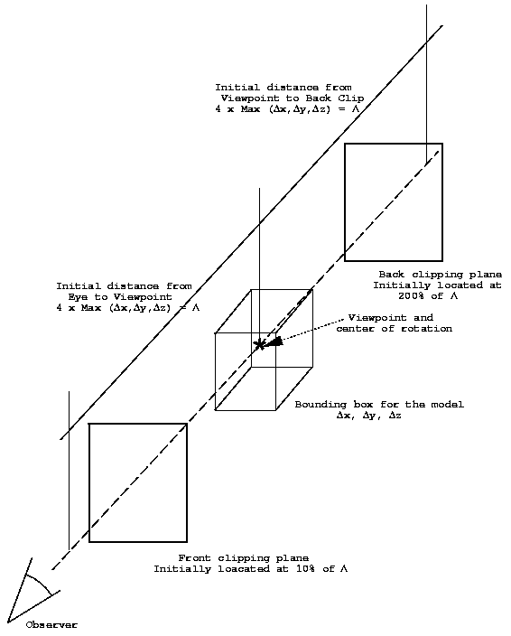
| 2. | There are a few additional graphics related terms which warrant additional comments (see Figure below). |
| • | bounding box - is a rectangular box with dimensions Dx by Dy by Dz which initially contains the model. |
| • | viewpoint - the center point of the bounding box initially containing the body. Note that the viewpoint always remains fixed in space and is also the center of rotation. |
| • | front clipping plane - is an imaginary plane initially located at ten percent of the distance form the observers eye to the center of the bounding box containing the body (viewpoint). The location of this plane may be adjusted using the Front Clip option found on the Views tab on the Viewport Control Form. As the clipping plane is moved toward the center of the bounding box, portions of the mesh, isosurfaces, etc., between the clipping plane and viewers eye are removed. The front clip plane may be placed anywhere from five percent to 199 percent of the distance from the observers eye to the center of the viewpoint. Percentages greater than 100 indicate the clipping plane is on the other side of the viewpoint. |
| • | back clipping plane - is an imaginary plane initially located at 200 percent of the distance form the observers eye to the viewpoint. The location of this plane may be adjusted using the Back Clip option found on the Views tab on the Viewport Control Form. As the clipping plane is moved toward the viewpoint, portions of the mesh, isosurfaces, etc., away from the observer are removed. The back clip plane may be placed anywhere from 200 percent to six percent of the distance from the observers eye to the center of the viewpoint. The location of this plane, however, must always be in back of the front clipping plane. |
| • | zoom - the zoom option as described above. It only changes the size of the object. |
| 3. | It is possible to become lost in space, especially for large complex domains. The ResetView `hot' button (the bulls eye icon on the top of the Main Viewport) returns the object to its initial position inside the Main Viewport, resetting the projection and clipping plane positions. |
See also
Main Viewport


