|
»Click here to display Table of Contents«
|

Graphics Options |

|

|

|

|
|
Graphics Options |
|
|
|

|
|
»Click here to display Table of Contents«
|
Graphics Options |
|
|
|
|
|
Graphics Options |
|
|
|
|
There are two tab forms including Graph Opts and Colorbar on the Viewport Control Form that may not be directly accessed from one of the icons on the top of the Main Viewport window. The Graph Opts panel provides option to set background color. In addition, models with symmetry boundary conditions can use the Mirror Mode option to display solution on complete geometry.
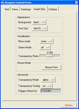
The Graphics Options panel
The Graph Opts tab on the Viewport Control Form contains three groups of options for controlling the appearance of images and text displayed in the Main, XY, and Slice Viewports. Except for Font Size and Background color, the rest of the options appearing on this form are only available in OpenGL and Mesa graphics modes (not XT mode). The functionality of each option on this form is described below.
Field |
Description |
Background |
Provides three options for color selection for the viewport background, black, gray, or white. This option is particularly useful when creating screen bitmap dumps. |
Font Size |
Selects a font size to use with all of the viewport windows. Currently there are only six helvetica fonts to choose from which range between 10 and 20 point. |
Mirror Mode |
For models with symmetry boundary conditions can use the Mirror Mode option to display solution on complete geometry by reflecting the solution and mesh about a selected plane of symmetry. |
Stereo |
Switches between normal (color) graphics, and a black-and-white 3D stereo image similar to old three dimensional movies. The use of this option requires inexpensive red-blue glasses (not provided with PHLEX). Glasses can be purchased from various sources. |
Transparency Ratio |
Sets the density of transparent surfaces (isosurfaces and slices in "transp" or "fog" mode, or the model boundary in transparent mode). A high value will create almost opaque surfaces, while a low value allows lots of "see-through". |
Mouse Mode |
Allows you to assign /reset the mouse controls. |
Transparency Mode |
Switches between "screen-door" transparency, and "true" alpha-transparency mode. Currently there are no graphics drivers with both modes implemented: XT mode uses screen-door, while OpenGL uses alpha transparency. |
Transparency Sorting |
To obtain realistic images, all transparent polygons have to be sorted from the back to the front of the screen. This sorting has to be done in software, and can considerably slow down the graphics for large models. Turning off transparency sorting speeds up the graphics at the expense of the image quality. It is advisable to switch to non-transparent mode rather than use this option. |
Polygon Offset Ext |
OpenGL was designed for photo-realistic images, and has difficulty in properly drawing lines on surfaces (e.g. boundary mesh on the solid model). Without the Polygon Offset Extension these lines will be usually drawn as discontinuous "stitches" (see Figure below), partially in front of the surface, and partially behind it (hidden). There is currently no "foolproof" way to control that functionality, as it depends on the model size and on the particular implementation of the graphics hardware. By default, this field contains two numbers: "1.5 1e-6". When the display of the solid mesh is unsatisfactory, your can experimentally adjust these numbers, usually by simply changing the exponent of the second number in the field. Some rules of thumb for adjusting the numbers include: 1. with discontinuous edges: increase the second value; 2. when the image shows edges which should not be visible: decrease it. Turns the color bar on and off, automatically scaled. |
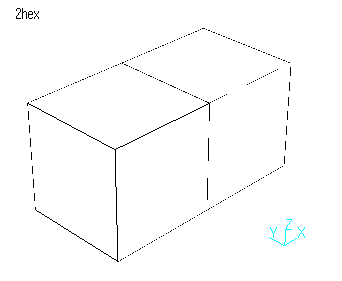
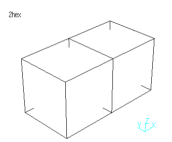
Discontinuous surface stitches effected by the polygon offset parameters