Boundary conditions in HyperXtrude are comprised of two entities:
| • | a load collector card image that defines the boundary data |
| • | a component collector to store the boundary faces. |
The HX solver requires that boundary conditions are specified on all the exterior boundary faces and interior faces between elements of different materials. Elements of each material should have boundaries defined on all its exterior faces. Hence at the interface of two element sets of two different materials, a boundary condition is required on each element set. It becomes important to distinguish a boundary face by its material type.
The Boundary Condition Editor opens when you click Create/Edit BC on the HyperXtrude Utility menu. The HyperXtrude Boundary Conditions Setup menu is displayed. The procedure for creating boundary conditions involves these steps:
| 1. | Create a new boundary condition by selecting its name, type, material, and color. |
| 2. | Edit the boundary condition data and fill in all the required parameters. |
| 3. | Assign this boundary condition to specific faces, by selecting the elements, nodes, and break angle. |
The Boundary Condition Editor walks you through these steps.
How Do I…
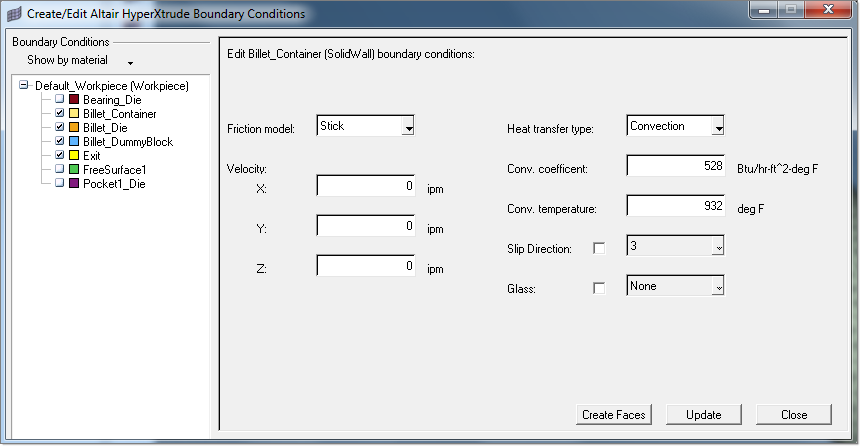
| 1. | From the HyperXtrude Utility menu, click Create/Edit BC. The Create/Edit Altair HyperXtrude Boundary Conditions dialog is displayed. |
| 2. | Click BCs. Data fields appear in the right side of the dialog. |
| 3. | Type a name in the Boundary Name field. |
| 4. | Select a type of boundary condition in the Boundary Type field. |
| 5. | Click Create. A boundary condition entity appears in the BCs tree in the left portion of the dialog and fields relevant to the boundary type you selected appear in the right portion of the dialog. In addition, a load collector of the same name you specified for the boundary condition is created. |
| 6. | Provide specification data for the boundary condition and click Update. |
The following options are also available on the Create/Edit Altair HyperXtrude Boundary Conditions dialog:
Create Faces
|
Helps you create BC faces.
|
Update
|
Updates changed information when editing an existing boundary condition. This is a required step.
|
Close
|
Closes the dialog.
|
|
| 1. | From the HyperXtrude Utility menu, click Create/Edit BC. The Create/Edit Altair HyperXtrude Boundary Conditions dialog is displayed. |
| 2. | Select a boundary condition from the BCs list on the left side of the dialog. Data fields appear in the right side of the dialog. |
| 3. | Click Create Faces. You are prompted to pick an element. Select an element in the interior region as shown below (not on an edge) on the face of choice and click proceed. The BC faces are created. |
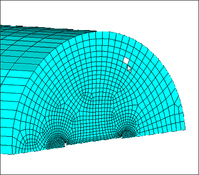
|
BCs can now be reorganized based on these options:
| • | type (type of boundary condition) |
| • | material (by material assigned to BCs) |
| • | all (this display all BCs only sorting them by name) |
Select from the following "Show by type", "Show all", " Show by material" to organize the BCs panel as follows.
BCs sorted by type:
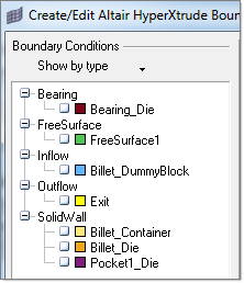
|
BCs sorted by materials:
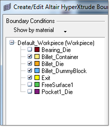
|
BCs sorted by name:
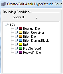
|
You can also check/uncheck the checkbutton before name of each boundary surface(refer above image) to turn ON/OFF display of BCs
|
See Also:
Defining Process Parameters


