|
»Click here to display Table of Contents«
|

Create Bearing Lines |

|

|

|

|
|
Create Bearing Lines |
|
|

|

|
|
»Click here to display Table of Contents«
|
Create Bearing Lines |
|
|
|
|
|
Create Bearing Lines |
|
|
|
|
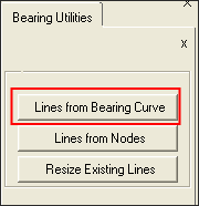
The Create Bearing Lines macro is used to create bearing lines from 3D-bearing curves.
Prerequisites for this feature:
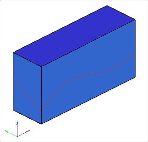
| • | 3D-bearing curves should touch bearing solids and should be stored in one single component. |
| • | If your model has more than one 3D-bearing curve (that is, if you have a hollow profile or a multihole die model) then each 3D-bearing curve should be stored in a separate component. |
The bearing lines created from this macro will be stored in a new component called xxx_lines (where xxx is name of 3D bearing curve component). Once you create bearing lines using 3D-bearing curves, the Extrusion Wizard will use these lines to create bearing profiles.
The BC Editor can create a bearing profile from control nodes or line. Most die makers, however, provide the bearing profile as a 3D curve along with the CAD data of the model. In order to use this information, the Create Bearing Lines macro provides a set of tools to create bearing lines from the 3D curve and manipulate them.
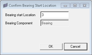
This macro will prompt you to select the component that has the 3D bearing curve defined. Each bearing profile is associated with a curve and each curve should be in a separate component. That is, if you have a 4 hole solid profile die, you will have four bearing curves (one for each hole) and each one of the curve should be in a separate component. These bearing curve components should have only the lines that make the bearing curve and nothing else.
|