In this tutorial, you will:
| • | Load the model and set the Moldflow user profile |
| • | Create component collectors and edit their card image |
| • | Trim the surface for enhancing mesh match |
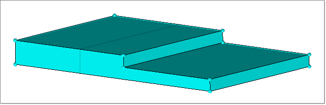
In this tutorial you will go over the process of setting up a basic fusion model for export to Moldflow using the Manufacturing Solutions HyperMold user profile. This is a simple model and design of runner system is not included in this tutorial.
| 1. | From the Start menu, select Altair HyperWorks > Manufacturing Solutions > HyperMold. |
| 2. | Click the Import Model icon  . . |
| 3. | Click the file browser icon  and browse to MF_0030.hm. and browse to MF_0030.hm. |
Note: The model files for this tutorial are located in the file mfs-1.zip in the subdirectory \HyperMold\moldflow\MF-0030. See Accessing Model Files.
|
This exercise explains the process of creating component collectors for the shell elements. For fusion mesh, the thickness value specified in the card is not used. Moldflow automatically estimates the thickness.
| 1. | Click Mesh > Create > Automesh. |
| 2. | Set the mesh type to trias to create 3-noded tria elements. |
| 3. | Enter the element size at 5.0 |
| 6. | Click return twice to accept the mesh and exit the panel. |
|
| 1. | Click Mesh > Check > Components > Edges. |
| 2. | Click the selector to change the option to elems. Click elems >> displayed. |
| 3. | Click on the find edges button to find the free edges in the model. A message displays: |

Your model should not have any free edges and should enclose a volume. If your model has free edges, you should inspect where the free edges are and correct it. This may happen if the elements are not connected or if you have non triangular elements.
| 4. | Click return to close the panel. |
|
Normal vectors of the elements selected for computing mesh match ratio should point inwards. If this requirement is not met, this computation will take a very long time before aborting.
| 1. | Click Mesh > Assign > Element Normals to open the Element Normals panel. |
| 2. | Select the elements subpanel. |
| 3. | Switch the toggle to elems and click elems >> displayed. |
| 4. | In the size = field, enter 5. |
| 5. | Click display normals to display the normals and ensure all the elements normals are inward. |
| 6. | You can complete the following optional steps, depending on the direction of the normal vectors. |
| a. | If all the normal vectors are outward, click on reverse normals to make all normals inward. |
| b. | If some of the normals outward and some are inward, adjust all the normals inward by clicking elems under orientation and picking any one of the elements with the inward normal. Click adjust normals to make all the normals inward. |
| 7. | Click return to exit the panel. |
|
| 1. | On the Utility menu, click Diagnostics. |
| 2. | Click Mesh Match Ratio. |
| 3. | In the Mesh Match Ratio dialog, click the Show contours checkbox. |
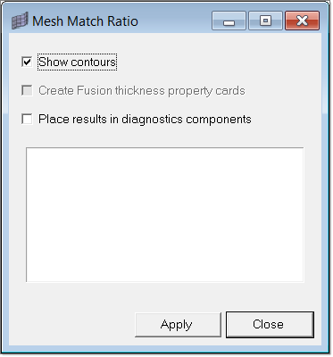
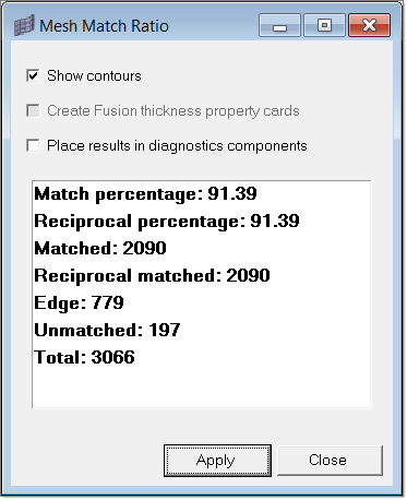
| 4. | Click Apply. The estimated values and the contour plot is displayed, showing the matching, unmatched and side elements. |
| 5. | Click Close, then click return to close the panel. |
|
| 1. | In the Utility menu, click Edit Prop Card. A new tab with tools to create and assign property cards opens. |
| 2. | Click Create & Assign Property Card. A dialog opens to select the property card name and type. |
| 3. | Set the following data: |
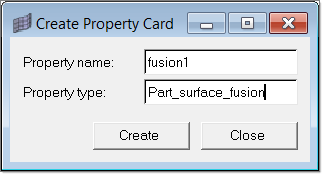
| 4. | Click Create. You are then prompted to select the elements and edit the property card. |
| 5. | Click elems >> displayed. |
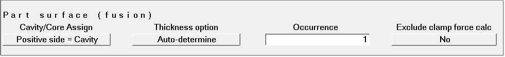
| 7. | In the card image, accept the default values and click return. This assigns the fusion1 property card to all displayed elements. |
|
| 1. | Under the Export Data group, click Moldflow. The Export Moldflow Data Files dialog appears. |
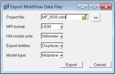
| 2. | Enter MF_0030.udm in the Project file field and/or specify a path to save the Moldflow file. |
| 3. | Select the format of Moldflow for which to create the file. |
| 4. | Select Millimeters for the HM model units field. |
| 5. | Select Displayed for the Export entities field. |
| 6. | Select Midplane for the Model type field. |
A Moldflow input file is now created in the location you specified. Import this file into Moldflow.
|
Return to Moldflow Tutorials


