This tutorial steps you through a simple example of creating a feed system (also known as a runner system) for Moldflow using the Moldflow profile in HyperMold.
In this tutorial you will:
| 1. | From the Start menu, select Altair HyperWorks > Manufacturing Solutions > HyperMold. |
| 2. | Click the Import Model icon  . . |
| 3. | Click on the file browser icon  and browse to MF_0020.hm. Copy this file to your working directory before beginning the tutorial. and browse to MF_0020.hm. Copy this file to your working directory before beginning the tutorial. |
Note: The model files for this tutorial are located in the file mfs-1.zip in the subdirectory \HyperMold\moldflow\MF_0020. See Accessing Model Files.
| 4. | Click Close to close the Import tab. |
This model already includes a midplane and lines that represent the feed system. These two steps are suggested as first steps to set up a feed system. For an example of how to create a midplane, refer to Introduction to the Moldflow Macro Menu tutorial.
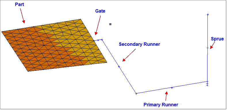
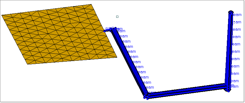
The completed model will be a multi-cavity mold with four parts.
|
This model includes lines that will be used to create a sprue, primary and secondary runners, and a gate. In this task, you will create the beam elements that comprise the feed system.
| 1. | Click Mesh > Create > Line Mesh. The Line Mesh panel opens. |
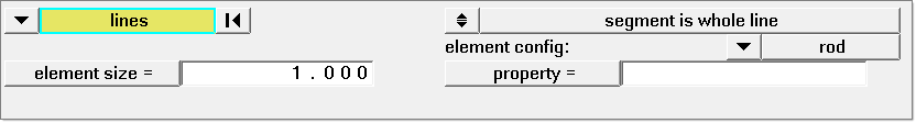
| 2. | In the element config: field, ensure that rod is selected. This selection is required for Moldflow output. |
| 3. | Click lines >> displayed. |
| 4. | Click mesh. Mesh is created for the lines in the model. |
You can adjust mesh density and other common characteristics of mesh as usual.
| 5. | Click return to accept the mesh and exit the panel. |
|
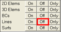
| 1. | On the Utility menu, click Off for the Lines. This setting makes element identification easier in the following steps. |
| 2. | Click Design Circuit>>> to open the sub-menu. |
| 3. | Under Create/Edit Feed System, click Create Feed System. The Create Feed System dialog appears. |
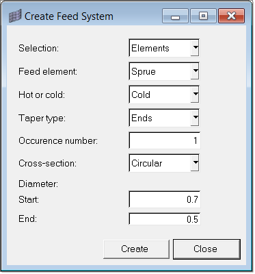
| 4. | Set the following options on the dialog. These settings are for the first component of the feed system. |
| • | Diameter end: 0.5 (where melt enters sprue from the extruder) |
| 5. | Click Create. Now you have to select elements in the main menu area. |
| 6. | Click elements >> by window. Create a closed shape around the elements in the sprue. |
| 7. | Click proceed and select a starting element. The starting element determines the direction of the taper, if you have created an element that tapers |
| 8. | Click proceed. Property cards are created for these elements. In addition, a solid is created depicting the shape of the solid. This solid is created only for the purpose of visualization. If you delete the solid, the underlying elements are not deleted and vice versa. However, when you use the Utility menu to modify elements, the solid and property cards are automatically re-created to reflect the changes. |
| 9. | Repeat steps 3 through 8, using the following settings for each additional feed system component: |
Primary Runner:
| • | Cross-section: Rectangular |
Secondary Runner:
| • | Cross-section: Rectangular |
Gate:
| • | Diameter end: 0.7 (where it touches the part) |
| 10. | Equivalence any coincident nodes. |
|
The node at the end of gate (where it touches the part) and the node it touches on the part have to be equivalenced. This is because the feed system mesh was created independently of the part mesh and these two nodes are different. You can do this from the Edges panel.
| 1. | Click Edges from the main menu area. |
| 2. | Click the switch to elems (instead of comps) and pick the displayed elements. |
| 3. | Set the tolerance as 0.01. |
| 4. | Click preview equiv to show the duplicate nodes. |
| 5. | Click equivalence to merge these nodes. |
|
| 1. | Return to the main Moldflow Utility menu by clicking the <<Back button. |
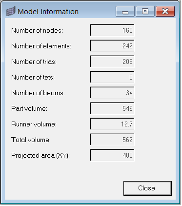
| 2. | Click Diagnostics followed by Summary. The Model Information dialog appears listing various statistics about the model, such as the number of nodes and elements, and the total volume for the part and the runners. When you are finished reviewing this information, click Close. |
| 3. | Return to the main Moldflow Utility menu by clicking <<Back. |
|
When you export a Moldflow data file, only the element information is used. Lines and surface data are not used.
| 1. | Under the Export Data group, click Moldflow. The Export Moldflow Data Files dialog appears. |
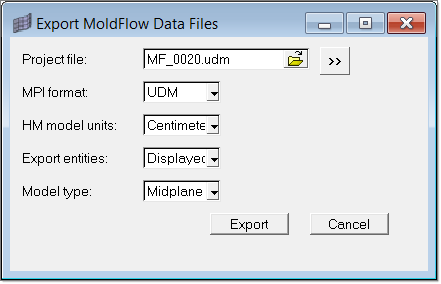
| 2. | Enter MF_0020.udm in the Project file field and/or click the button to specify a path to save the Moldflow file. |
| 3. | Select the format of Moldflow for which to create the file. |
| 4. | Select Centimeters for the HM model units field. |
| 5. | Select Displayed for the Export entities field. |
| 6. | Select Midplane for the Model type field. |
A Moldflow input file is now created in the location you specified. Import this file into Moldflow.
|
Return to Moldflow Tutorials


