This tutorial introduces you to the Moldflow macro menu available in Manufacturing Solutions. This tutorial steps you through the processes of loading a model, creating a mesh, checking element quality, and exporting the data deck for Moldflow analysis.
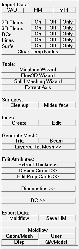
The Moldflow macro menu simplifies the use of the Moldflow user profile in order to quickly set up an analysis model. The buttons in the macro menu consist of customized panels that are specific to Moldflow and shortcuts to a few commonly-used HyperMesh panels. The buttons are presented in the same order as you need them, from top to bottom.
Overview
The following is a summary of steps followed in this tutorial:
| 3. | Generate mesh on the midsurface |
| 4. | Transfer thickness data from midsurface to elements |
| 9. | Export the Moldflow data deck |
This exercise uses the model file MF_0010.hm.
Note: The model files for this tutorial are located in the file mfs-1.zip in the subdirectory \HyperMold\moldflow\MF-0010. See Accessing Model Files.
|
| 1. | From Altair HyperWorks > Manufacturing Solutions choose the HyperMold user profile. |
| 2. | To load the model, click on the open .hm file icon  and browse to MF_0010.hm and browse to MF_0010.hm |
The Moldflow interface supports three types of input file types: HyperMesh files, external CAD files (see the Import documentation for a listing of supported CAD types), and Moldflow input decks (MPI files).
|
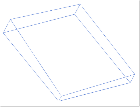
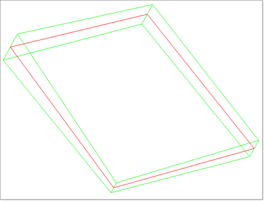
Following the order of the macro menu, you would first clean up the model’s geometry. However, in this simple example, the geometry is already acceptable. Next, extract the midsurface representation of the solid part.
| 1. | Click Geometry > Create > Midsurfaces > Auto. |
| 2. | Click the yellow surfs button and select displayed from the extended selection menu. |
| 3. | Click extract to create the midsurface. |
| 4. | Click return to exit the panel. |
|
For feed systems, click Create and Edit in the Lines group to create lines. However, feed systems are not needed in this example. The next task is to create mesh elements on the midsurface you just created. Note that only linear triangular elements (trias/tria3) are supported
| 1. | Click Mesh > Create > 2D Automesh to open the Automesh panel. |
| 2. | Set the mesh type: field to trias. |
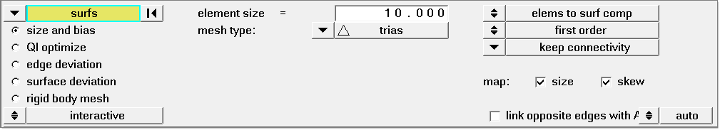
| 3. | In the graphics area, click on the midsurface to select it. |
| 4. | In the element size field, enter 0.5. |
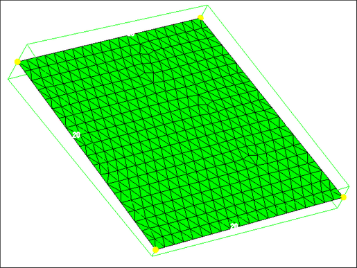
| 5. | Click mesh to create the mesh. |
| 6. | Click return to exit the panel. |
|
Once the mesh has been created, extract the element thickness data from the midsurface plane to the elements.
| 1. | In the Utility menu, under the Edit Attributes heading, click Extract Thickness. The Extract Midsurface Thickness dialog appears. |
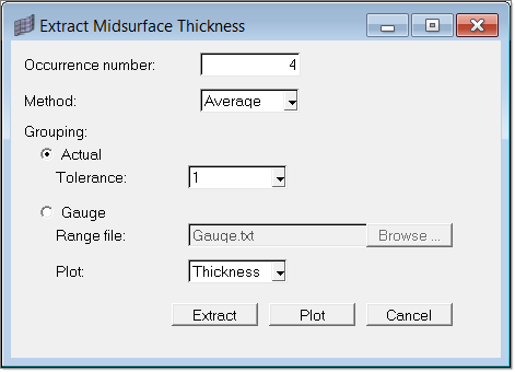
| 2. | In the Occurrence number field, type 4. |
| 3. | In the Method field, select Average. |
| 4. | Select Actual for Grouping and type a value of 1 in the Tolerance field. |
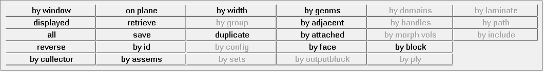
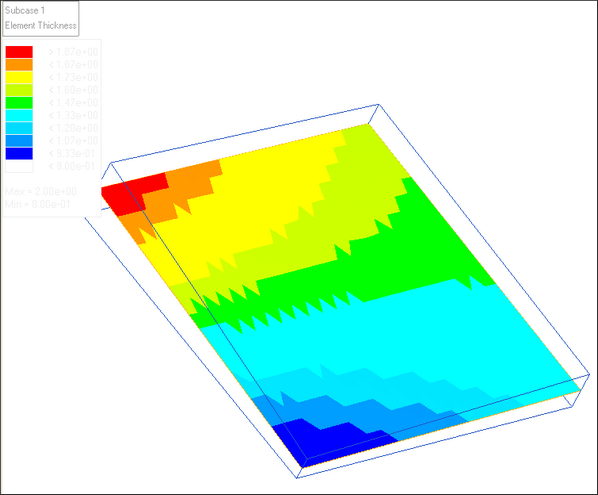
| 6. | Next, select a surface from which the elements’ thickness should be extracted. In the element selector panel, click elems >> by collector and select Middle Surface. |
| 7. | Click proceed to create property cards with thickness, eccentricity, and occurrence number and assign them the elements on the selected midsurfaces. A contour plot of element thicknesses displays. |
|
Now you can create feed systems or cooling circuits in the model. However, in this exercise, skip to the quality checks.
| 1. | In the Utility menu, click Diagnostics>> to open a sub-menu for element diagnostics. This menu provides many checks, such as overlapping elements, element thickness distribution, aspect ration, element property. |
| 2. | Click Aspect Ratio. Aspect ratios are calculated based on Moldflow’s formula, which is different from HyperMesh’s formula. A contour plot appears that displays the aspect ratios. |
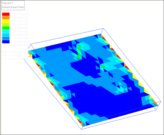
For midsurface models, Moldflow requires aspect ratios less than 10. You can see in the contour plot that the largest aspect ratio in this model is 2.37.
| 3. | Click Summary to view a list of statistics about the model. The information appears in the Model Information dialog. |
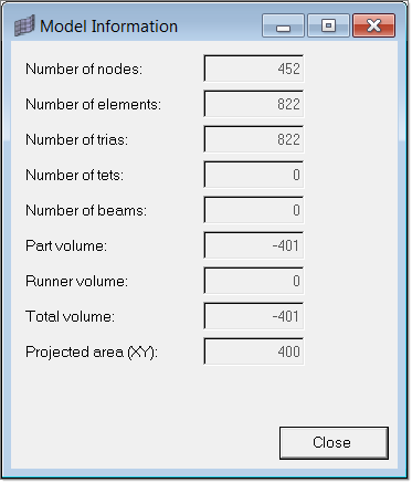
| 4. | Click Close to close the dialog. |
| 5. | Click return to close the panel. |
| 6. | Click Back>> to return to the Moldflow Utility menu. |
|
At any time you can create or edit the property cards for the model by clicking Edit Prop Cards under the Edit Attributes group. From the submenu, click Edit Property Card to change an existing property or click Edit Element Data to change the property associated with an element.
|
This is an optional step. Sometimes you may be interested in grouping/organizing your elements into component collectors based on its properties. With this dialog, you can categorize elements into different groupings based on thickness or element type.
| 1. | Click Diagnostics >> Organize Elements. The Organize Elements dialog appears. |
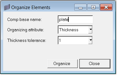
| 2. | In the Comp base name field, type plate. In the Organizing attribute field, select Thickness, and select 1 for the Thickness tolerance field. |
| 3. | Click Organize. A selection panel appears from which you can specify which elements to organize. |
| 4. | Select elems >> displayed. Click proceed. The elements are organized into 13 new components based on thickness. The names of the new components are generated by combining both the component base name you provided and the thickness value for that grouping. |
|
The last task in this tutorial is to export the Moldflow data deck.
| 1. | Under the Export Data group in the Utility menu, click Moldflow. The Export Moldflow Data File dialog appears. |
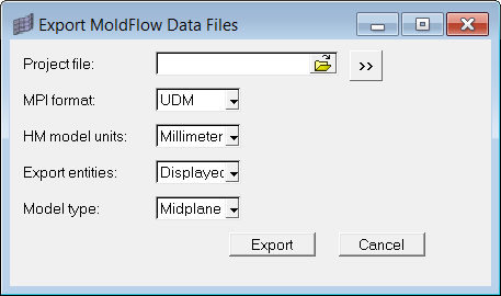
Export Moldflow Data Files
| 2. | Click the button to browse to the location to save the file, specify a file name in the File Name field, and click Save. |
| 3. | Select the other parameters for the file, including the Moldflow version, units of measure, which entities to export, and the type of the model. |
| 4. | Click Export. A Moldflow file (*.udm) is created in the location you specified. This data file can be opened in Moldflow. |
|
Return to Moldflow Tutorials


