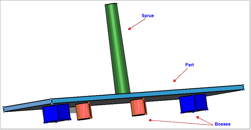
In this tutorial, you will set up a solid 3D mesh model for Moldflow. During this tutorial, you will also learn how to use the Flow3D Wizard to quickly set up the model. You will start from solids to create this mesh. By appropriately merging the solids and/or sharing the common surfaces, you can control how the mesh is generated. For example if the gate is modeled as a solid, then the gate solid should only share the surface with the part solid. This way the mesh generated for the gate will be in a separate component and it can be excluded for the warpage calculations.
| 1. | From the Start menu, select Altair HyperWorks > Manufacturing Solutions > HyperMold. |
| 2. | Click the File Open icon  and browse to MF_0050.hm. and browse to MF_0050.hm. |
Note: The model files for this tutorial are located in the file mfs-1.zip in the subdirectory \HyperMold\moldflow\MF-0050. See Accessing Model Files.
|
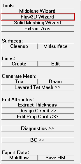
| 1. | On the Utility menu, click Flow3D Wizard. |
|
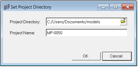
| 1. | In the tab, click Set Project Directory. Specify the project directory and project name and click OK. |
|
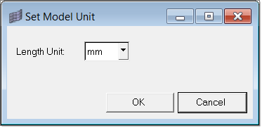
| 1. | In the tab, click Set Model Unit. Select the model length unit in the dialog and click OK. |
|
| 1. | In the tab, click Solid Edit to do share/merge operations on the solids in the model. |
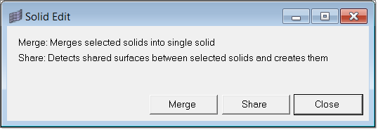
| 2. | Click Merge to select the solids and merge them into single solid. The selector panel opens. |
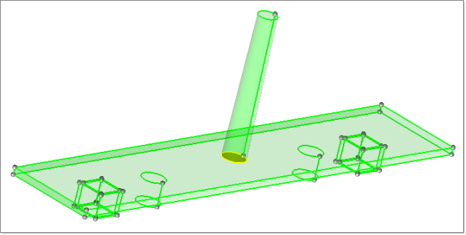
| 3. | Select the solids in the collectors base and bosses_merge. |
| 4. | Click proceed. The merged solids are placed in either base or bosses_merge. The Solid Edit dialog reopens after each Merge/Share operation to provide additional solid edit opportunities. |
| 5. | In the Model browser, rename the collector that has the solid (in this case, it should be bosses_merge) as part and delete the other (empty) collector. |
| 6. | In the Solid Edit dialog, click Share to create shared surfaces between part and the solids in collector bosses_share. The purpose of this exercise is to show that even with the part, you can have multiple solids, and thereby meshes can be created in multiple collectors. |
| 7. | Click Merge again select the collectors part and bosses_share. |
| 8. | Click proceed to create shared surfaces between the solids. The Solid Edit dialog opens again. |
| 9. | Click Share to share the surfaces between the part and the sprue. It is mandatory that the feed system mesh remains separate from the part mesh. |
| 10. | When the selector panel opens, select the solids in the part and sprue. |
| 11. | Click proceed to create the shared surfaces between the solids. |
| 12. | Click Close to close the Solid Edit dialog. |
|
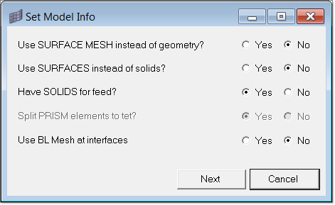
| 1. | Click Set Model Info. Set the options as shown below and click OK. |
In this model, there are only solids. One advantage of starting with solids is that you can mesh the feed system with tet4 elements using this macro. However, this option is not supported if you start with either surfaces or surface mesh.
| 2. | Click Next to open the Select Components dialog. |
| 3. | Select the part and bosses_share components in the left panel and click Add to Part. |
| 4. | Select sprue and click Add to Feed. |
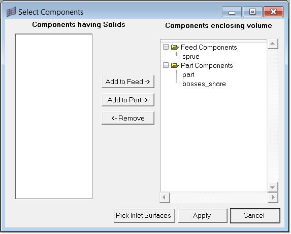
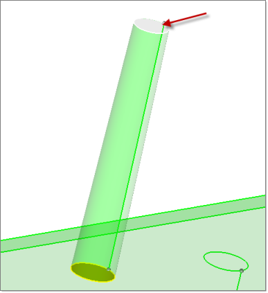
| 5. | Click Pick Inlet Surfaces and pick the melt entry surface on the top of sprue solid. Click proceed. |
| 6. | Click Apply to close the dialog. |
|
| 1. | In the Flow3D Wizard, click Surface Mesh. This opens the Surface Mesh dialog. |
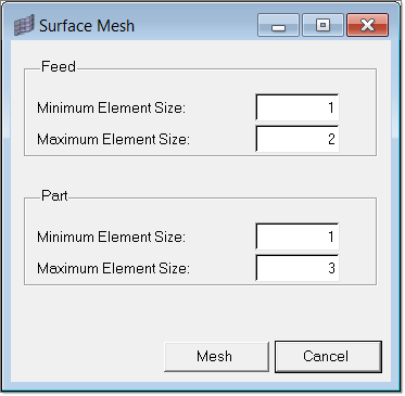
| 2. | Set the size as shown in the image above and click Mesh to create a surface mesh. |
|
| 1. | In the Flow3D Wizard tab, click Volume Mesh. The Flow3D Mesh dialog opens. |
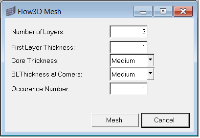
| 2. | Accept the default values and click on Mesh. |
|
| 1. | Click Export Data in the Flow3D Wizard. The Export Moldflow Data Files dialog appears. |
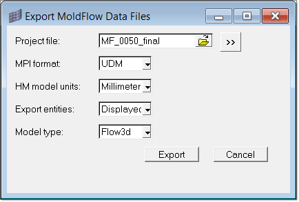
| 2. | Click Export to export the model. |
| 3. | Click Close to close the Flow3D Wizard. |
This deck can be imported in Moldflow Plastics Insight(MPI) and solved.
|
Return to Moldflow Tutorials