In this tutorial, you will set up a solid (3D) model for Moldflow starting from a CAD file having surfaces. For generating the solid mesh, a closed set of surfaces always need to be considered. If the surfaces selected don’t form a closed loop, the boundary layer generation will fail. During this exercise, you will also learn how to use the Flow3D Wizard to quickly set up the model.
| 1. | From the Start menu, select Altair HyperWorks > Manufacturing Solutions > HyperMold. |
| 2. | Click the File Open icon  and browse to MF_0051.hm. and browse to MF_0051.hm. |
Note: The model files for this tutorial are located in the file mfs-1.zip in the subdirectory \HyperMold\moldflow\MF-0051. See Accessing Model Files.
|
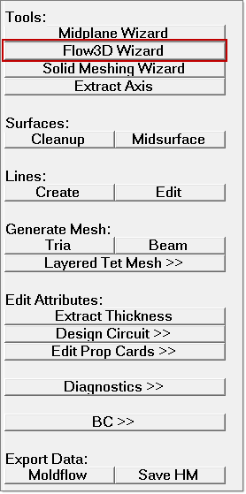
| 1. | On the Utility menu, click on Flow3D Wizard. |
|
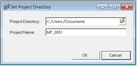
| 1. | In the tab, click Set Project Directory. Specify a project directory and a project name and click OK. |
|
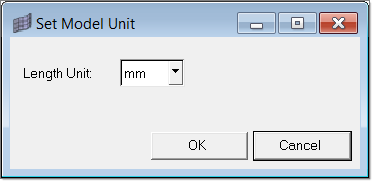
| 1. | In the tab, click Set Model Unit. Select the model length unit in the dialog and click OK. |
|
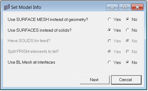
| 1. | Click Set Model Info. Set the options as shown below and click Next. |
|
| 1. | Select the surface components and add them as volumes in the Select Components dialog. |
| • | Select base1, boss1_shared, and boss2_shared as a new volume |
| • | Select boss1 and boss1_shared and add them as a new volume |
| • | Select boss2 and boss2_shared and add as a new volume |
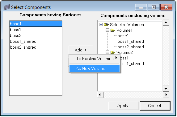
| 2. | Click Apply to save the information and close the dialog. |
|
| 1. | In the tab, click Surface Mesh. The Surface Mesh dialog opens. |
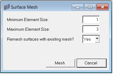
| 2. | Select the minimum and maximum size as 1 and 3 mm; and then click Mesh. This creates a surface mesh on the surfaces of the selected volumes. A mesh is created on all the surfaces in the model. |
|
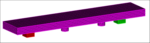
| 1. | In the tab, click on Volume Mesh. The Flow3D Mesh dialog opens. |
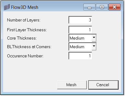
| 2. | Accept the default value and click Mesh. The actual layer thickness to be used will be automatically recomputed if the selected value is too high. It will take few seconds to create the 3D mesh. The newly created 3D mesh is placed in the component collectors flow3d_mesh0, flow3d_mesh1 and flow3d_mesh2. |
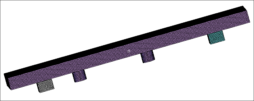
| 3. | Click on the Model tab and expand the Component folder. |
| 4. | Right-click on the components flow3d_mesh0, flow3d_mesh1 and flow3d_mesh2 and click Show. All the 3D elements are shown. |
|
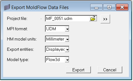
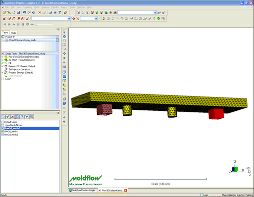
| 1. | Click Export in the Flow3D Wizard. The Export Moldflow Data Files dialog appears. |
| 2. | Click Export to export the model. |
| | This deck can be imported in Moldflow Plastics Insight(MPI) and solved. |
|
Return to Moldflow Tutorials