In this tutorial, you will learn how to:
| • | Load a HyperMesh file containing the solid geometry of the runner |
| • | Edit and organize the runner geometry |
| • | Create the runner mesh using the Runner Mesh Wizard |
| • | Inspect the mesh quality |
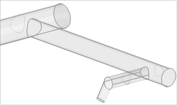
To use the Runner Meshing Wizard, the runner solid geometry has to be segregated into two categories. Runner solids that can be meshed by prism elements (tubes), and those that can be meshed by tetrahedral elements (junctions of tubes). This ensures that a high quality solid runner mesh is created for the runner system using the Runner Meshing Wizard.
The model files for this tutorial are located in the file mfs-1.zip in the subdirectory \HyperMold\Moldex3D\MX_1040. See Accessing Model Files.
To work on this tutorial, it is recommended that you copy this folder to your local hard drive where you store your HyperXtrude data, for example, “C:\Users\Moldex3D\” on a Windows machine. This will enable you to edit and modify these files without affecting the original data. In addition, it is best to keep the data on a local disk attached to the machine to improve the I/O performance of the software.
| 2. | On the Preferences menu, click User Profiles. |
| 3. | In the Application field, select Manufacturing Solutions. |
| 4. | Select HyperMold and Moldex3D/Solid. |
|
| 1. | From the File menu, click Open. |
| 2. | Browse to the file MX_1040.hm. |
| 4. | Click on the Shaded Geometry icon  to display the model as shaded. to display the model as shaded. |
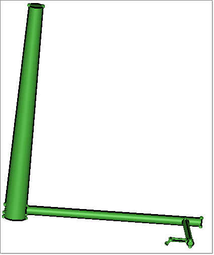
| 5. | Click on the Model tab to view the contents of the file. The runner solid geometry is in a component collector named RunnerSolid. |
| 6. | From the Tools menu, select Count. The Count panel opens. |
| 7. | Change the selector of the collector to solids.  |
| 8. | Click displayed. In the solids field, the value of 1 is shown, signifying that there is only one solid in the model. |
| 9. | Click return to close the panel. |
|
| 1. | Click solid edit in the main menu. The Solid Edit panel opens. |
| 2. | Select the trim with plane/surf subpanel. |
| 3. | Click solids >> with plane and select the solid from the graphics area. Set the selector switch below the solids collector to z-axis. The button B signifying the base node is activated. |
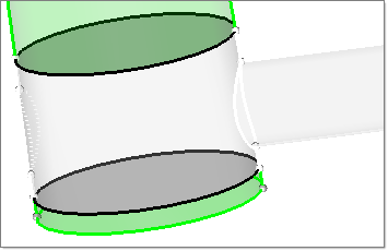
| 4. | Using the + key on the keyboard or the mouse, zoom to the area where the sprue is branching into a runner as shown below. |
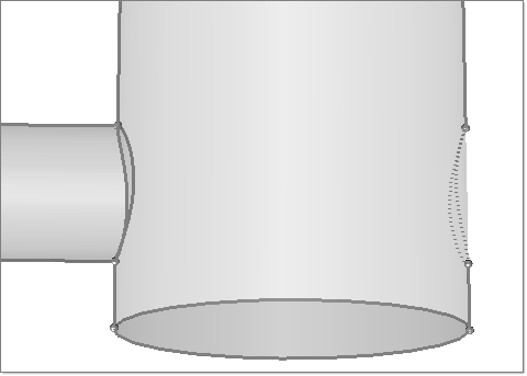
| 5. | Click anywhere in the graphics area. Left-click and drag the mouse pointer towards the solid such that the left edge is selected as shown below. |
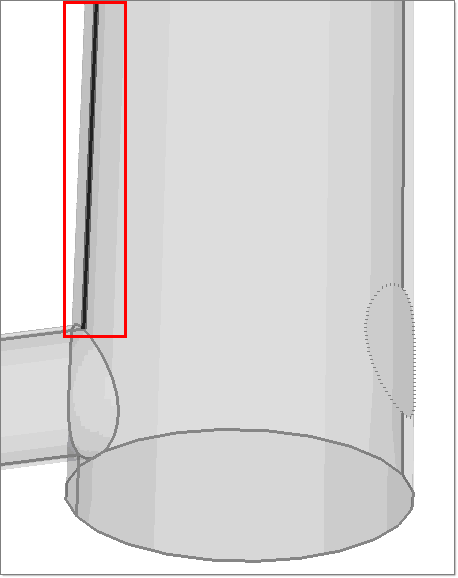
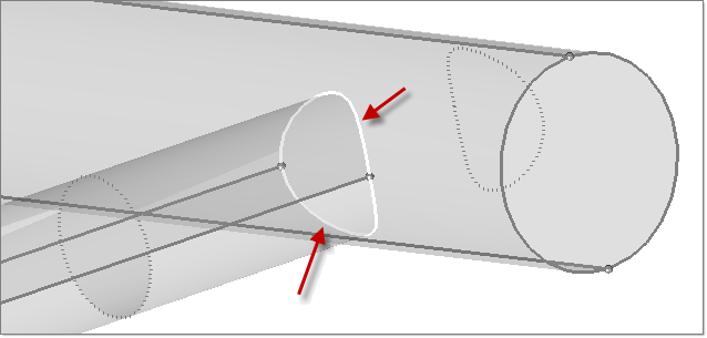
| 6. | Click on the edge just above the junction as shown below. The location selected is the base node of the plane. |
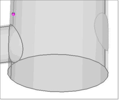
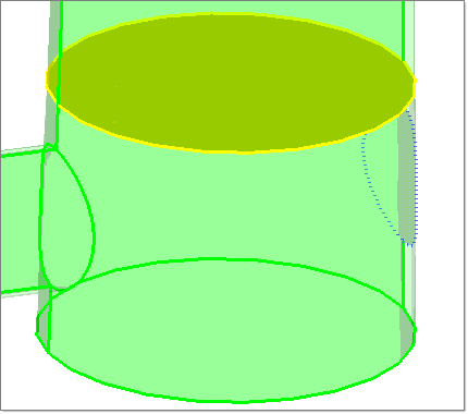
| 7. | Click trim. Notice a shared surface (yellow colored) is created. That signifies that the solid has been trimmed and a new solid is created. To confirm, repeat steps 5 through 7 above. This time there are two solids. |
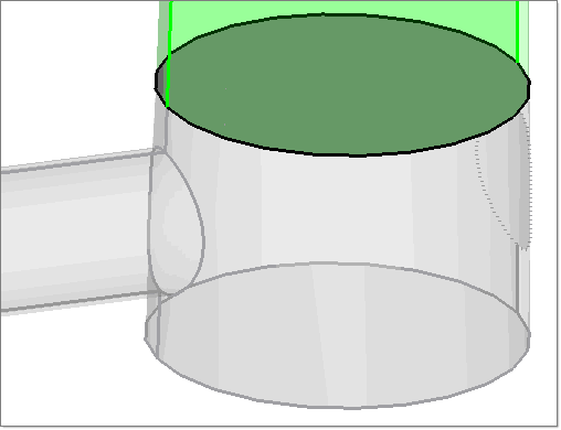
| 8. | Select the solid as shown below. |
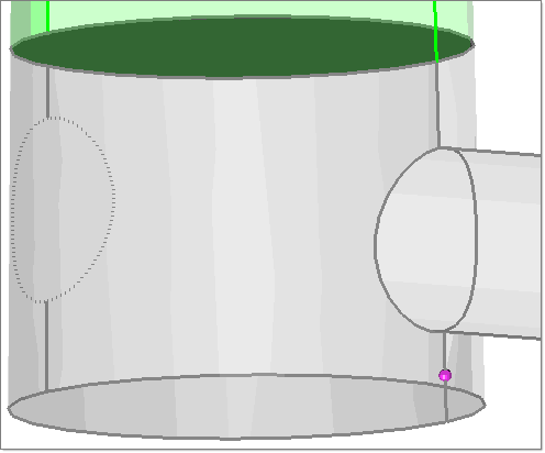
| 9. | Repeat the steps 5 and 6. This time select the edge below the junction as shown below. Select the base node location at a distance from the junction so that the elements are not squeezed. |
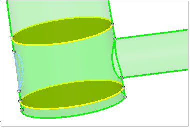
| 10. | Click trim. Notice that another shared surface is created. Now the total number of solids is 3. The junction is one single solid. The objective of editing solid is to split the single runner solid into solids at the junctions as shown above and pipes or tubes. |
| 11. | In the same panel, select the subpanel trim with lines. |
| 12. | Under the section with bounding lines:, click solids to activate it, and then select the solid as shown below: |
| 13. | Click lines. Select the lines as shown below. These are lines that connect the runner and the sprue. |
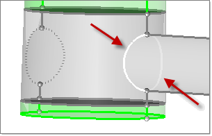
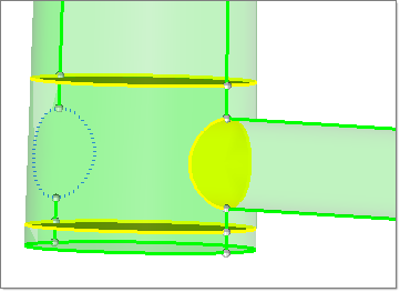
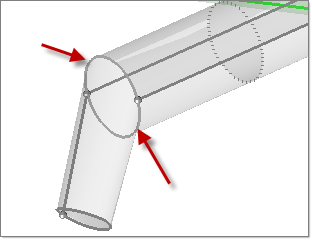
| 14. | Click trim. Notice the shared surface created at the intersection of the sprue and the runner, as shown below. |
| 15. | As the primary and the tertiary runner are parallel, if you trim the second junction using the plane option, then the tertiary runner also is trimmed. So, separate the tertiary runner and the gate solid first. Using the view controls, zoom to the junction of secondary runner and tertiary runner as shown below. |
| 16. | Select the solid as shown below: |
| 17. | Click lines again, and select the lines as shown below: |
| 18. | Click trim. The solid is trimmed. Notice the shared surface created. |
| 19. | Using the view controls, zoom to the gate area as shown below. |
| 20. | Repeating the steps performed above, select the solid and then select the lines shown below: |
| 21. | Click trim. Notice the share surface created. |
| 22. | Click return to exit the panel. Click F5 on the keyboard to open the Mask panel. Set the selector to solids. |
| 23. | Select the tertiary runner and the gate solid from the graphics area. Click mask. The solids display is switched off. Click the return button to exit the panel. |
| 24. | Click solid edit again. Repeat the steps 4-10 for the second junction. For the with plane option, select x-axis. |
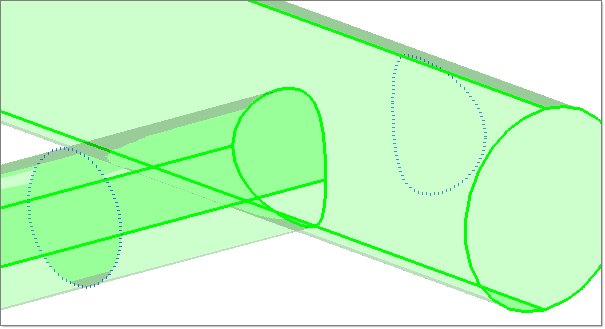
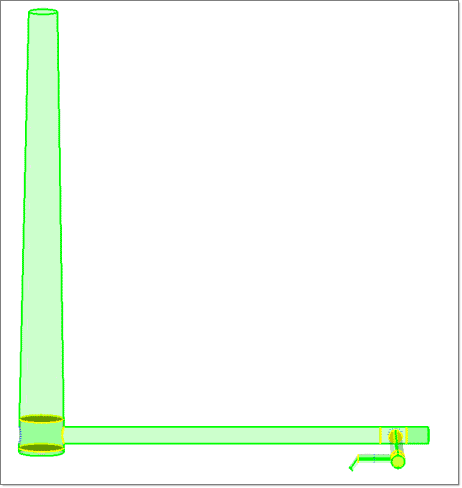
| 25. | Repeat the steps 4-10 for the third junction. For the with plane option, select y-axis. After these steps, the runner geometry looks as shown below. There should be 11 solids and 10 shared surfaces. |
|
| 1. | In the Model tab, right click in the white space and select Create > Component. The Create component dialog opens. |
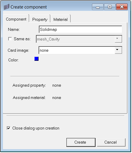
| 2. | Specify the name as Solidmap. Click Create. A new component is created. |
| 3. | Repeat the steps 1-2. This time specify the name as Tetramesh. |
| 4. | From the main menu, click organize. The Organize panel opens. |
| 5. | Set the selector switch of the collector to solids. |
| 6. | Click dest component = and pick Solidmap. |
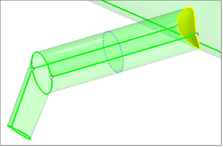
| 7. | Select the solids from the graphics area as shown below: |
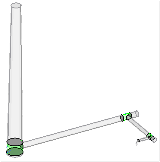
| 8. | Click move. The selected solids are moved to the Solidmap collector. |
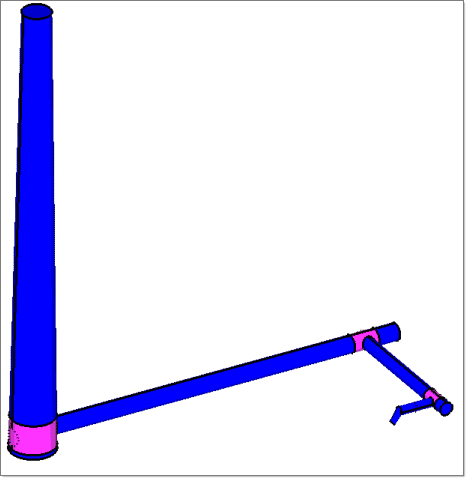
| 9. | Now select the remaining solids from the graphics area. Set dest component = to Tetramesh. |
| 10. | Click move again. The solids are organized to these two collectors. |
| 11. | Click return to close the panel. |
|
| 1. | On the Utility menu, click Runner Meshing Wizard. The Select Components dialog opens. |
| 2. | Select the Solidmap component from the left list. Click Solidmap to add the component to Meshed by Solidmap. |
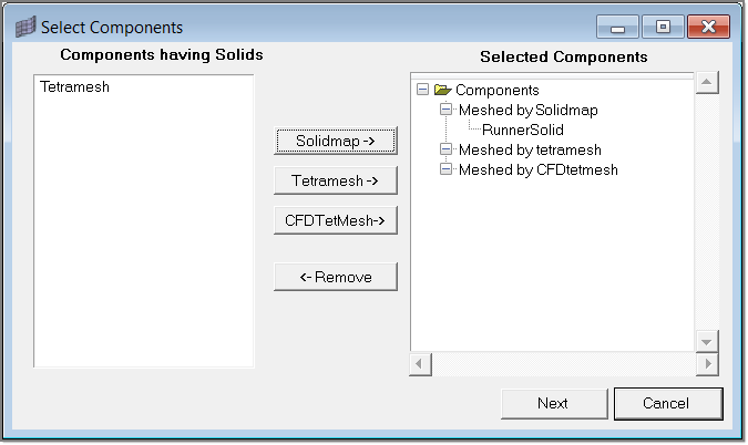
| 3. | Now select the Tetramesh component and click Tetramesh. The component selection is complete. |
| 4. | Click Next. The Meshing dialog appears. The selected components are shown with default element sizes. Default element sizes are shown for the solids in the component as well. The element size for a component is the minimum element size among the element sizes of the solids in that component. Clicking on a solid will highlight the solid in the graphics area. Changing the element size of the component will scale the element sizes of the solids accordingly. |
| 5. | Inspect the element sizes. When satisfied, click OK to start the meshing process. |
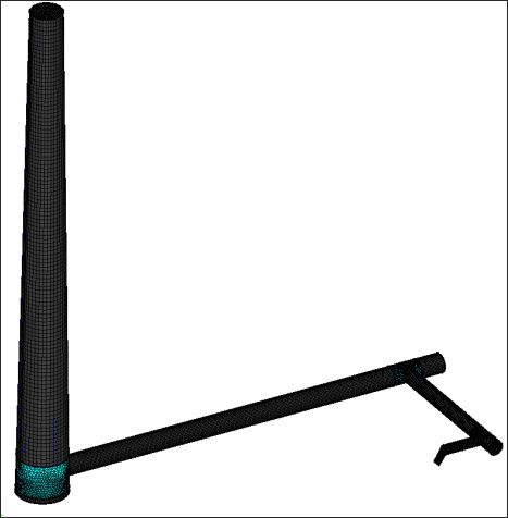
Meshing will take some time. A status window shows the status of meshing. The solidmap mesh is placed in a component collector named RunnerSolidMap3D and the tetramesh is placed in a component collector named RunnerTetMesh3D.
|
After completing the meshing in the previous step, the Mesh Quality Table is displayed automatically.
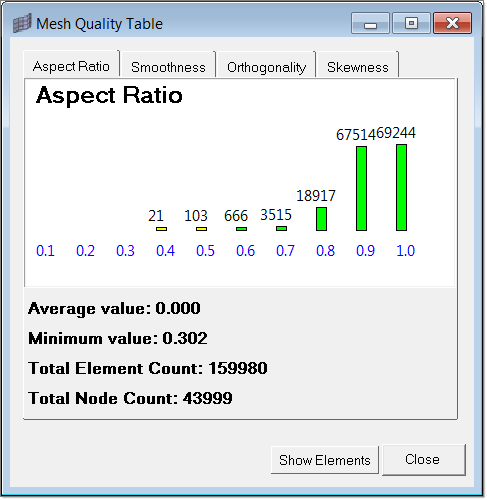
| 1. | Inspect all the attributes of the runner mesh. |
|
This tutorial is now complete.
Return to Moldex3D Tutorials


