Manufacturing Solutions

RTM Tutorial

RTM Tutorial

Previous topic This is the last topic Expand/collapse all hidden text  

RTM Tutorial

Previous topic This is the last topic JavaScript is required for expanding text JavaScript is required for the print function  


hmtoggle_plus1greyStep 1: Load the RTM user profile
1.Start HyperMesh Desktop.  
2.From the menu bar, click Preferences > User Profiles or click userProfile-24 on the Standard toolbar.
3.Click Manufacturing Solutions > HyperMold > RTM.  
4.Click OK.

The Utility browser opens.

rtm_utility_browser

hmtoggle_plus1greyStep 2: Load the model file

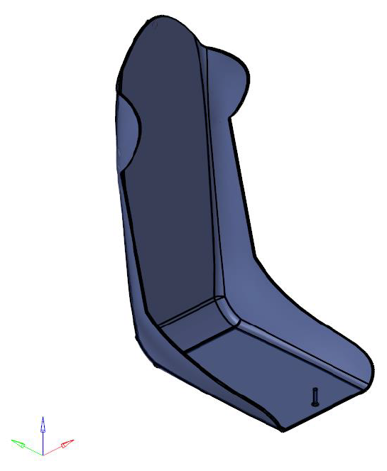
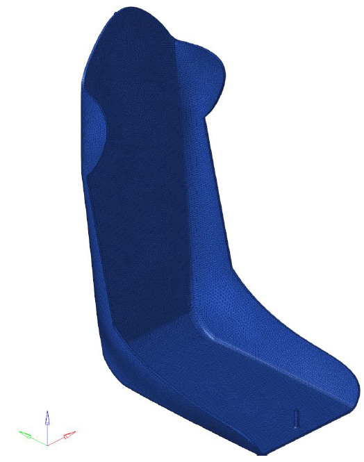
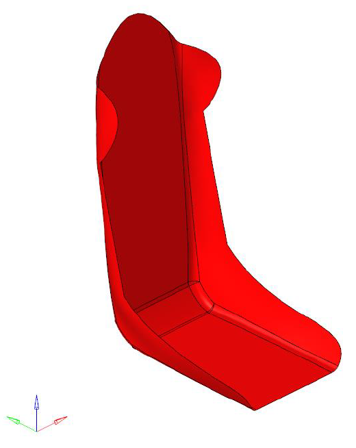
The model file contains 3D geometric information of the seat.

1.From the File menu, click Open.
2.Browse to the file seat_model.hm.
3.Click Open.

A model opens containing the geometry data.  

rtm_model

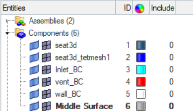
Use the Model Browser to view the model structure while providing full find, display and editing control of the entities. If the Model Browser is not already open, from the menu bar, click View > Model Browser.  

In seat_model.hm the solid seat geometric information is organized in a component collector called frpseat3d.  

rtm_model_browser

hmtoggle_plus1greyStep 3: Mesh seat using Solid Meshing Wizard

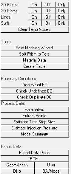
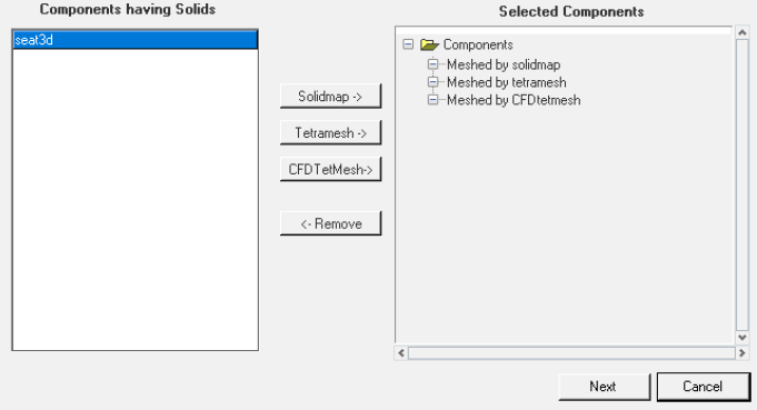
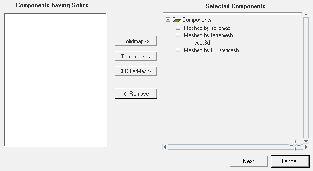
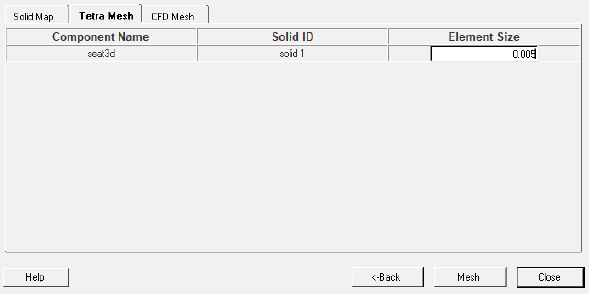
In this step you will create automatic tetra mesh of the seat model. The Solid Meshing Wizard is used to create a solid mesh model data deck for RTM analysis starting from solids.

The model file seat_model.hm contains 3D geometric information of the seat.  

1.Open the Solid Meshing Wizard tool. The dialog lists all of the components that contain the solids, and empty selected components.    

rtm_solid_meshing_model

Solid Meshing Wizard

2.Select the seat3d component and click TetraMesh to add them to the respective mesh type.  

rtm_selected_components

seat3d component selected for tetra mesh

3.Click Next.

A dialog opens.  

rtm_input_mesh_data

Input mesh data

4.Select the Tetra Mesh tab. Keep the Element Size of 0.005 for the seat3d component and click Mesh.    

The meshed seat model is generated and organized in a new component collector called seat3d_tetmesh1.

5.Click Close.  

rtm_seat_model

Mesh seat model

hmtoggle_plus1greyStep 4: Select a material from the database

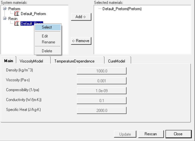
In this step you will select materials for the model and assign them to the appropriate components.  

1.From the RTM Utility menu, click Material Data.

A dialog opens.  

2.Using the tree in the upper-left portion of the dialog, expand the System materials to find the material you want to select.
3.Select Default_Preform and click Add, or right-click the material and click Select.
4.Select Default_Resin and click Add.

The material appears in the Selected materials.

rtm_material_assignment

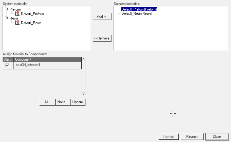
Material assignment

5.   Right-click Default_Preform and select Assign Material.

A table opens in the Material Database Editor.

rtm_dialog

Assign material to component

6.  Activate the seat3d_tetmesh1 checkbox to apply Default_Preform material.

7.  Click Update.

The material shows a tree view in the Selected materials list. When the material item is expanded, the components that use the material are listed.  

hmtoggle_plus1greyStep 5: Define boundary conditions

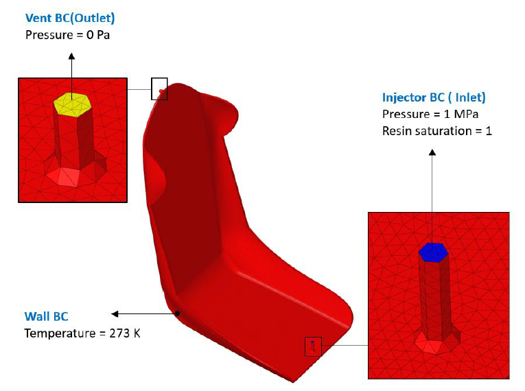
In this step you will create boundary conditions on the seat model. The boundary condition in RTM has two entities; a load collector card image that defines the boundary and a component collector to store the boundary faces. The Boundary Condition Editor is used to create boundary conditions on faces.  

In the seat model there are specific boundary conditions that need to be specified.

Inlet injector boundary condition (Pressure = 1 Mpa, Resin saturation = 1)
Outlet vent boundary condition (Pressure = 0 Pa)
Wall boundary condition

rtm_simulation

RTM simulation boundary conditions
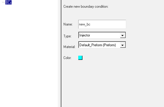
1.From the RTM Utility menu, click Create/Edit BC under Boundary Conditions.

A dialog opens.

2.Click BCs.

Data fields appear in the dialog.  

rtm_boundary_conditions_dialog

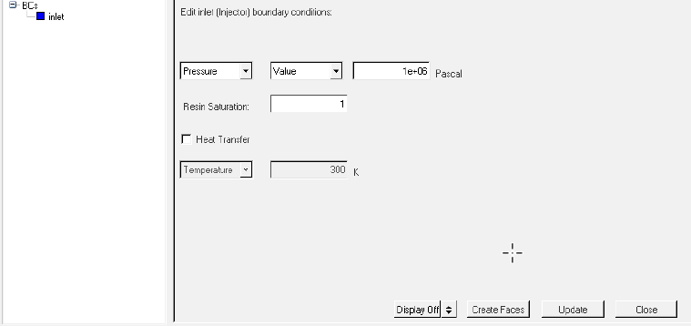
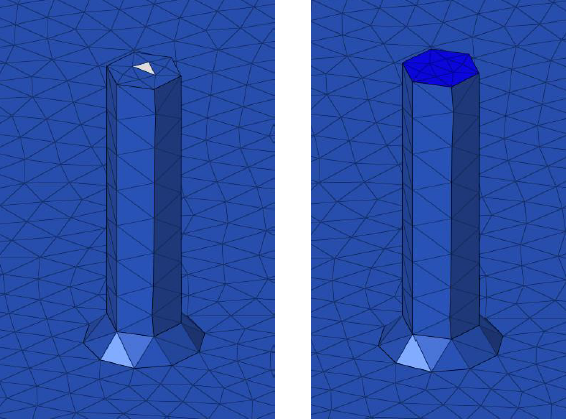
3.   To create inlet boundary conditions:

Type Inlet in the Boundary Name field.
Select the injector boundary condition in the Boundary Type field.
Click Create. The inlet entity appears in the BCs tree and fields relevant to the injector type BC also appear. A load collector of the inlet for the boundary condition is created.  
Enter the Pressure value as 1 Mpa and Resin Saturation as 1.

rtm_inlet_boundary_condition

Inlet boundary condition

Click Create Faces to create boundary faces.
Use the Element selection entity panel to select an element on the face, not on the edge. Select an element on the interior region of the inlet and click proceed. Inlet boundary faces are created.

rtm_face_creation

Element selection for inlet BC face creation

4.   To create outlet boundary conditions:

Click BCs.
Type vent in the Boundary Name field.
Select the vent boundary condition in the Boundary Type field.
Click Create. The vent entity appears in the BCs tree and fields relevant to the vent type BC also appear. A load collector of the vent for the boundary condition is created.  
Enter pressure value, 0 pascal.

rtm_vent_boundary_condition

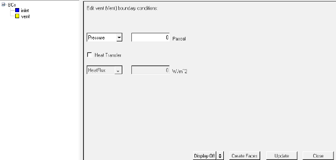
Vent boundary conditions

Click Create Faces to create the boundary face for the vent boundary condition.


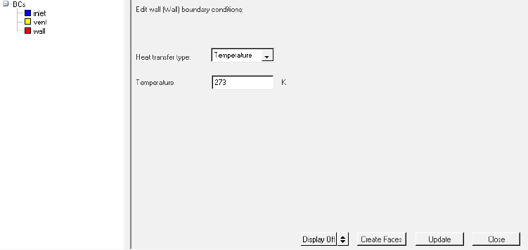
5.   To create wall boundary conditions:

Click BCs.
Type wall in the Boundary Name field.
Select the vent boundary condition in the Boundary Type field.
Click Create. The wall entity appears in the BCs tree and fields relevant to the wall type BC also appear. A load collector of the wall for the boundary condition is created.

rtm_wall_boundary_condition

Wall boundary condition

Enter 273 K temperature as the wall surface temperature.
Create boundary face for the wall boundary condition in a similar way as mentioned for inlet BC.
.

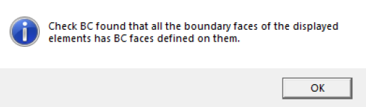
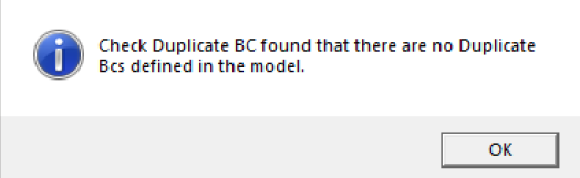
Note: Before proceeding to the next step, run a check for undefined and duplicate BCs.


1.Click Check Undefined BC. Make sure that the boundary condition is defined on all of the boundary faces of the elements.

rtm_boundary_faces

2.Click Check Duplicate BC.  

rtm_no_duplicate

hmtoggle_plus1greyStep 6: Select process parameters

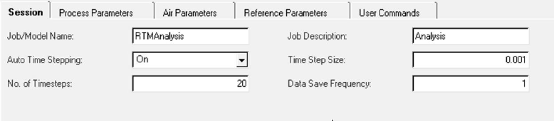
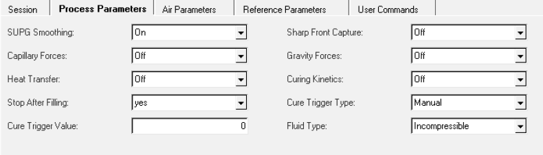
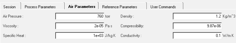
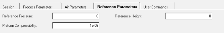
In this step you will setup process parameters. The process parameters allow you to control the run by specifying the equations/physics to be solved and defining control parameters, such as convergence tolerance and number of iterations/time steps.  

1.Click Parameters on the RTM Utility menu.
2.Set general analysis data.

rtm_session

3.Set process specific data.

rtm_process_parameters

4.Set Air Parameters.

rtm_air_parameters

5.Set Reference Parameters.

rtm_reference_parameters

6.Click Close.
hmtoggle_plus1greyStep 7: Select the OptiStruct user profile

In this step you will load the OptiStruct user profile. Draping analysis is performed in OptiStruct. Resin transfer molding consists of mainly two process draping analysis and RTM simulation.

1.Start HyperMesh Desktop.
2.From the menu bar, click Preferences > User Profiles or click userProfile-24 on the Standard toolbar.  
3.In the User Profile dialog, select OptiStruct from the HyperMesh application.
4.Click OK.
hmtoggle_plus1greyStep 8: Extraction of midsurface from 3D geometry

Midsurfaces can be extracted for sheet metal stampings, molded plastic parts with ribs, and other parts that have a thickness smaller than width and length.

During midsurface extraction, the original geometry that you select to extract the midsurface from remains unchanged, and the new geometry that represents the midsurface is created. The (variable) thickness of each middle surface is calculated and stored with the surface definition.

You can either create the midsurface from the seat model or you can import it.

1.Go to the Geom page and select the Midsurface panel.  
2.Select the auto extraction subpanel. Using the selector you can either select surfaces or solids to extract the midsurface from the model. Select the solids selector and choose solids for extracting midsurfaces.
3.After solid selection click extract to create midsurfaces.

A midsurface representation of a solid part of solid geometry is generated and organized in a new component collector called Middle Surface.

4.To accept the Middle Surface, click return.

rtm_model_browser2

rtm_extracted_midsurface

Extracted midsurface

5.Right-click the Middle Surface component and rename it seat2d.


hmtoggle_plus1greyStep 9: Mesh midsurfaces

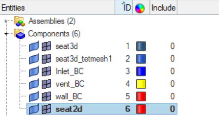
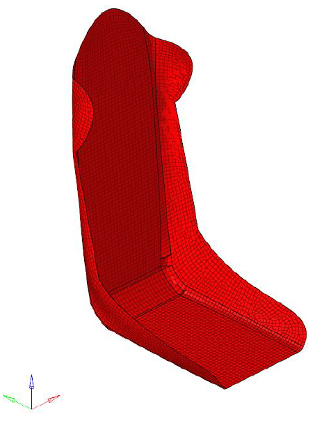
In this step, you will set the mesh parameters and create CQUAD4 mesh on the midsurface created in the previous step.

Note: The RTM solver supports only quad mesh for the draping operation.

1.In the Model Browser, if seat2d is not the current component, right-click the seat2d component collector and select Make Current.

Note: The seat2d component collector is now the current component collector, and any component created will be placed in this collector.

rtm_seat2d

2.Open the Automesh panel for 2D meshing. To open the panel, from the menu bar, click Mesh > Create > 2D AutoMesh or press F12.
3.Go to the size and bias subpanel.
4.Verify that the entity selector is set to surfs and select the surfaces for meshing. Select all surfaces in the seat2d component collector.
5.Set element size to 0.01.  
6.Select mesh type to quads only.
7.Set the first toggle to elems to current comp.
8.Click mesh.

HyperMesh opens the density subpanel in the meshing module. The model displays a node seeding and a number on each surface edge. The number displayed in the graphics area is the number of elements that were created along the edge.  

9.To accept the mesh as the final mesh, click return from the Density panel, and click return again from the Automesh panel.


rtm_meshed_component

Meshed component

hmtoggle_plus1greyStep 10: Creation of system for draping analysis

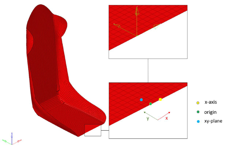
Use the Systems panel to create a rectangular coordinate system.

1.To create a system collector, from the menu bar, click Collectors > Create > System Collector, or right-click in the Model Browser and select Create > System Collector from the context menu.
2.To create a system, open the analysis page and select the Systems panel.
3.Select reference nodes for system creation, select the origin node, x-axis reference node and xy-plane reference node. Click create to create a new system.
4.Click return.  

rtm_system_creation


System creation

hmtoggle_plus1greyStep 11: Ply creation for draping analysis

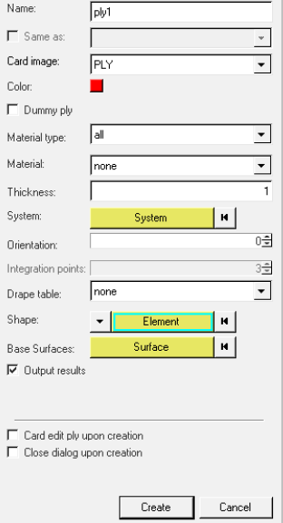
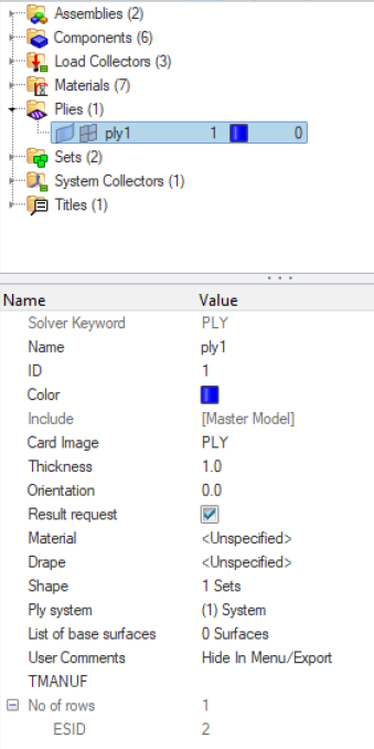
In this step you will generate two plies of unit thickness.

1.To create a ply, from the menu bar, click Properties > Create > Plies, or right-click in the Model Browser and select Create > Ply from the context menu.
2.Go to the Create Ply subpanel.
3.Enter the ply name as ply1.
4.Select card PLY as the card image.
5.Set thickness as 1 unit.
6.Set Orientation as 0.
7.Select system created in step 5 as System.
8.Select all elements associated with the component collector seat2d for shape using element method.

rtm_create_ply

9.Click Create to create the ply.

In the Model Browser, a new ply and an element set that consists of all the elements selected to define the shape of the ply will be added.

10.In the Model Browser, Plies folder, click ply1.

The Entity Editor opens and displays the component’s corresponding data. You can change this data, if needed.

rtm_entity_editor_plies

11.Repeat the steps to create another ply named ply2 with 90-degree orientation.  
hmtoggle_plus1greyStep 12: Open Drape Estimator

In this step you will perform drape calculation.

The preform is characterized in the lay-flat orientation. This characterization can be done in either of the following coordinate-systems: oblique, cylindrical, spherical. For the seat model, permeability is known in the Cartesian system. To produce a part of the desired shape, the unsaturated preform is draped on the mold before the resin infusion. To accurately perform the RTM simulation, you need to determine the permeability of the preform in the global coordinate system by taking into account the effect of the mold geometry.  


1.To open the Drape Estimator, right-click the Plies folder in the Model Browser and select Drape > Drape Estimator from the context menu.
2.Select the Drape Calculation tab.
3.Set Initial Drape Direction as By Ply System.  
4.Set the ply system origin node as Seed Point.
5.Click Apply to perform drape calculation.
6.You can review drape thickness, drape orientation, shear angle and flat shape using the review option in the Drape Estimator. You can export drape calculation information as a geometric file as well.

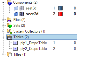
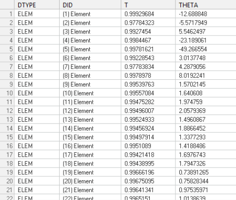
Once the Drape Estimator has finished generating the drape data, HyperMesh creates a drape table for each selected ply inside the Tables folder in the Model Browser.

rtm_tables

7.Review and edit the data generated by the Drape Estimator in the Entity Editor by selecting a drape table in the Model Browser. To review the drape data for this table, click pencil_icon2. The drape data available in this table includes: DTYPE, DID, T and THETA. It contains information about thinning due to draping (T) and the difference between fiber orientation and draping fiber orientation (THETA) for each element.  

rtm_drape_table

Review drape table

hmtoggle_plus1greyStep 13: Create a laminate

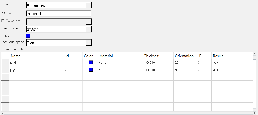
In this step you will create a laminate.

1.To create a laminate, from the menu bar, click Properties > Create > Laminate, or right-click in the Model Browser and select Create > Laminate from the context menu.
2.Enter the laminate name and select the ply details.
3.Click create to create the laminate.

rtm_create_laminate

hmtoggle_plus1greyStep 14: Export data deck

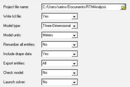
In this step you will export the RTM data deck.

1.Open the RTM user profile.
2.Click Export Data Deck in the RTM Utility menu.
3.Select the location to export the data files.
4.Set Include drape data as Yes.
5.Set the other parameters as follows:

rtm_export_data_files

6.  Click Export.

hmtoggle_plus1greyStep 15: Run simulation

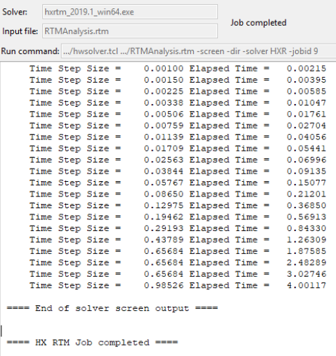
In this step you will perform RTM simulation.

1.Open HyperWorks Solver Run Manager (OptiStruct).

rtm_solver_run

2.Click Input file(s) and select the RTMAnalysis.rtm file from the export directory.
3.Click Run.

With a successful launch of the run, you can monitor the status of the simulation.  

rtm_solver_view