In this tutorial, you will learn how to:
| • | Load a HyperMesh file containing solid mesh of the part and the runner and geometry of coolant channel and moldbase |
| • | Create mesh for the coolant channel and moldbase |
| • | Assign property card(s) to the part and the runner |
| • | Assign property card to the moldbase surface mesh |
| • | Create the coolant channel |
| • | Define melt entrance boundary condition |
| • | Export the model as a Moldex3D MFE file |
In fast cool analysis, the meshes for moldbase, coolant channel and mold insert are not solid meshes. Mesh for coolant channel is a 1D mesh. Meshes for moldbase and mold insert are surface meshes. Meshes for part and runner are solid meshes.
The model files for this tutorial are located in the file mfs-1.zip in the subdirectory \HyperMold\Moldex3D\MX_1030. See Accessing Model Files.
To work on this tutorial, it is recommended that you copy this folder to your local hard drive where you store your HyperXtrude data, for example, “C:\Users\Moldex3D\” on a Windows machine. This will enable you to edit and modify these files without affecting the original data. In addition, it is best to keep the data on a local disk attached to the machine to improve the I/O performance of the software.
| 2. | On the Preferences menu, click User Profiles. |
| 3. | In the Application field, select Manufacturing Solutions. |
| 4. | Select HyperMold and Moldex3D/Solid. |
|
| 1. | From the File menu, click Open. |
| 2. | Browse to the file MX_1030.hm. |
| 4. | Click on the tab Model to view the contents of the file. |
| • | The part solid mesh is in the component collector mesh_Cavity. |
| • | Cold runner solid mesh is in the component collector mesh_ColdRunner. |
| • | Hot runner solid mesh is in the component collector mesh_HotRunner. |
| • | Coolant channel lines are in the collector geom_CoolChannel. |
| • | Heating rod lines are in the collector geom_HeatingRod. |
| • | Moldbase solid geometry is in the collector geom_Moldbase. |
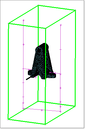
|
| 1. | Click on the Model tab to open the Model browser. Select geom_CoolChannel under the Component branch. Right click and select the option Make Current. |
| 2. | Click Coolant Channel Line in the Utility menu. The Line Mesh panel opens. |
| 3. | Click lines >> by collector. Select the collector geom_CoolChannel. |
| 4. | Set the element size field to 30. Click mesh. |
| 5. | Click return twice to exit the panel. |
| 6. | In the Model browser, right-click on geom_HeatingRod and select Make Current. |
| 7. | Repeat the steps 2 through 5 for the component collector geom_HeatingRod that has the lines for heating rod. |
| 8. | In the Model browser, right-click on geom_MoldBase and select Make Current. |
| 9. | Click Surface Mesh in the Utility menu. The Automesh panel opens. |
| 10. | Click surfs >> by collector. Select the collector geom_MoldBase. |
| 11. | Set the element size field to 150. Change the switch to elems to current comp from elems to surf comp. Click mesh to generate the mesh for the Moldbase. |
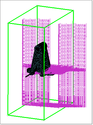
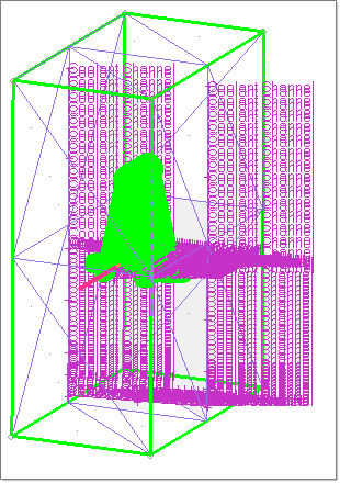
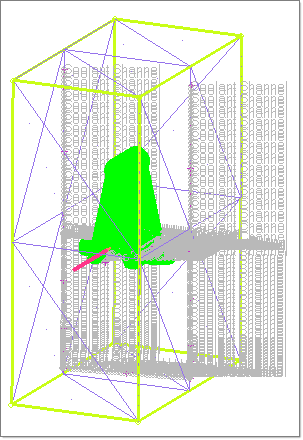
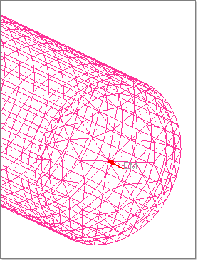
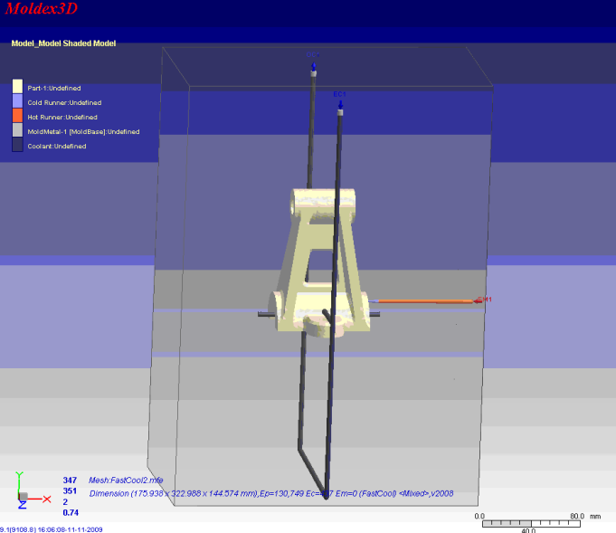
| 12. | Click the Wireframe Elements icon  to display the model as shown below: to display the model as shown below: |
|
| 1. | In the Utility menu, click Create Property Cards. |
| 2. | Click Solid Mesh. A panel to select the elements opens. |
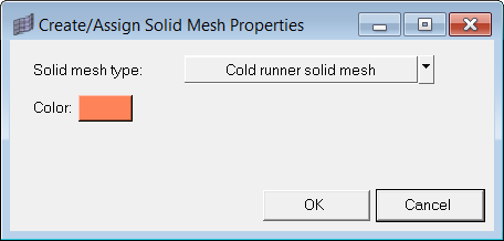
| 3. | Select the elements in the collector mesh_ColdRunner and click proceed. |
| 4. | Select Cold runner solid mesh from the drop-down menu and click OK. |
| 5. | Repeat the steps 1 - 4. This time select mesh_HotRunner component collector and Hot runner solid mesh in the Create/Assign Solid Mesh Properties dialog. |
| 6. | Repeat the steps 1 - 4. This time select mesh_Cavity component collector and Cavity (Part) solid mesh in the Create/Assign Solid Mesh Properties dialog. |
|
| 1. | In the Utility menu, under Fast Cool Analysis, click Surface Mesh. |
| 2. | Click elems >> by collector and select the collector geom_MoldBase. Click proceed. The Create/Assign Surface Mesh Properties dialog is displayed. |
| 3. | Retain Moldbase surface mesh as the Surface mesh type. Change the color if desired, and click OK to close the dialog. |
|
| 2. | Select the elements in the collector geom_CoolChannel and click proceed. The Create Coolant Channel dialog is displayed. |
| 3. | Set the Radius field to 2.0. |
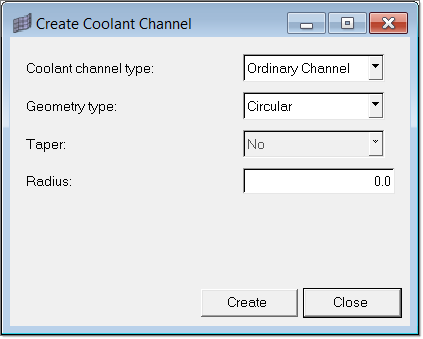
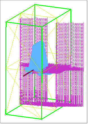
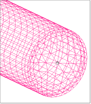
| 4. | Click Create to complete the coolant channel property creation and assignment. The creation of surfaces for visualization will take couple of seconds. |
| 5. | Click Coolant Channel again. |
| 6. | Select the elements in the collector geom_HeatingRod and click proceed. |
| 7. | Set the Coolant channel type to Heating Rod and set the Radius to 2.0. |
| 8. | Click Create to complete the heating rod property creation and assignment. Creation of surfaces for visualization will take couple of seconds. |
|
| 1. | In the Utility menu, under BCs:, click Point. A node selection panel opens. |
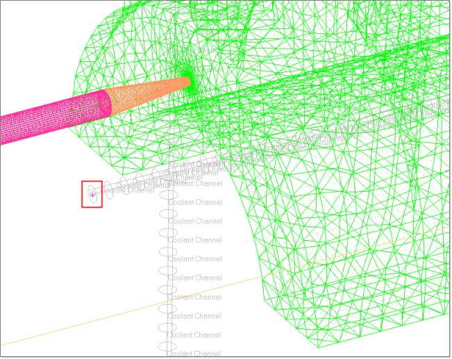
| 2. | Select a node on the hot runner from the graphic area as shown below and click proceed. The Create Boundary Condition dialog appears. |
| 3. | Select Melt Entrance for BC type. Click OK. Notice the boundary condition on the node. |
| 4. | Click Points again. Select the top most node of the coolant channel as shown below. Select Coolant Entrance as the BC type. Click OK to close the dialog. |
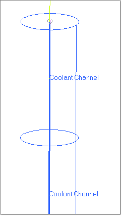
| 5. | Repeat step 4. Select the other topmost node of the coolant channel Coolant Entrance as the BC type. Click OK to close the dialog. |
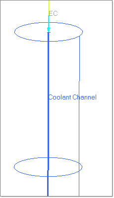
| 6. | Click Point again. Select the node on the heating rod towards the runner system as shown. Click proceed. The Create/Assign Point BCs dialog displays. |
| 7. | Select the BC type as Coolant Entrance. Click OK to close the dialog. |
|
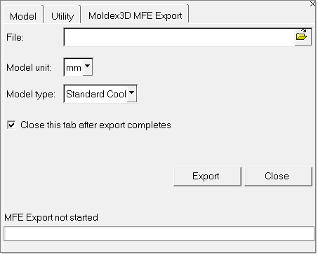
| 1. | Click Export. A new tab labeled Moldex3D MFE Export opens. |
| 2. | Specify the file path and name to write the MFE file. Set the Model type as Fast Cool and click Export. |
The status of the export is shown in the status bar.
|
| 1. | Load the exported MFE file in Moldex3D solver. |
|
Return to Moldex3D Tutorials


