In this tutorial, you will learn how to:
| • | Load a HyperMesh file containing solid geometry of the part and the runner |
| • | Create CFD mesh for the part and runner using Moldex3D Wizard |
| • | Assign property card(s) to the part and the runner |
| • | Define melt entrance boundary condition |
| • | Export the model as a Moldex3D MFE file |
The model files for this tutorial are located in the file mfs-1.zip in the subdirectory \HyperMold\Moldex3D\MX_1020. See Accessing Model Files.
To work on this tutorial, it is recommended that you copy this folder to your local hard drive where you store your HyperXtrude data, for example, “C:\Users\Moldex3D\” on a Windows machine. This will enable you to edit and modify these files without affecting the original data. In addition, it is best to keep the data on a local disk attached to the machine to improve the I/O performance of the software.
| 2. | On the Preferences menu, click User Profiles. |
| 3. | In the Application field, select Manufacturing Solutions. |
| 4. | Select HyperMold and Moldex3D/Solid. |
|
| 1. | From the File menu, click Open. |
| 2. | Browse to the file MX_1020.hm. |
| 4. | Click on the Shaded Geometry icon  to display the model as shaded. to display the model as shaded. |
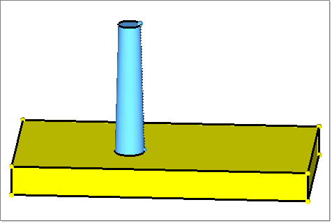
| 5. | Click on the Model tab to display the Model browser and view the contents of the file. The part geometry is in the component collector part. The runner geometry is in the component collector runner. |
|
| 1. | Click Moldex3D Wizard in the Utility menu. A new tab named Moldex3D Wizard opens. |
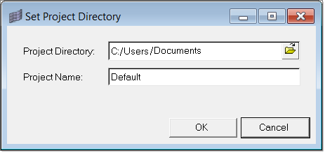
| 2. | Click on the checkbox Set Project Directory in the Moldex3D Wizard. The Set Project Directory dialog opens. |
| 3. | Specify the Project Directory and the Project Name. Click OK. |
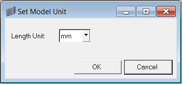
| 4. | Click on the checkbox Set Model Unit. The Set Model Unit dialog opens. Select the appropriate unit from the drop down field. Click OK. |
| 5. | Click the Geometry Color Mode icon  and set the display to By 3D Topo mode. and set the display to By 3D Topo mode. |
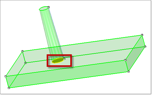
| 6. | Click on the checkbox Solid Edit. The Solid Edit dialog opens. Using this dialog, you can merge or share solids. As there is no shared surface between the part and the runner, a shared surface between these two solids must be created. |
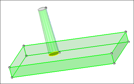
| 7. | Click Share. A panel to select the solids opens. Select both the solids from the graphics area and click proceed. Notice the yellow area that represents the shared surface between the part and runner. Click Close. |
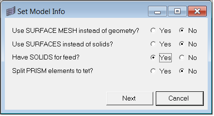
| 8. | Click on the checkbox Set Model Info. The Set Model Info dialog opens. Information about the model is set in this step. Set the options as shown below and click Next. The Select Components dialog appears. |
| 9. | Specify the components that contain the geometry of part and the feed (runner) system. On the left side is the list of components in the model with solids. On the right side, components are shown under part and feed categories based on the selection. |
| 10. | Select the component part and click Add to Part. Select the component runner and click Add to Feed. |
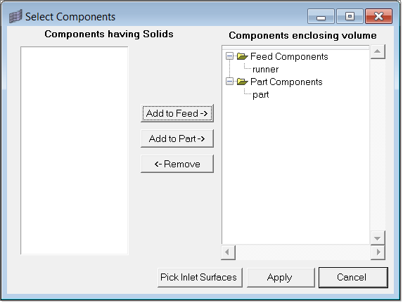
| 11. | Click Pick Inlet Surfaces to specify the feed inlet surface. A panel to select the surfaces opens. Select the top most surface of the runner as shown below. Click proceed and click Apply to set the information and close the dialog. |
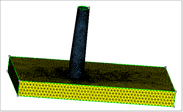
| 12. | Click on the checkbox Surface Mesh. The Surface Mesh dialog opens. Specify minimum and maximum element sizes separately for the part and the runner, as shown below. Surface meshing is done progressively from surface(s) with the smallest area until the surface with the largest area. A good surface mesh yields a good quality solid mesh. |
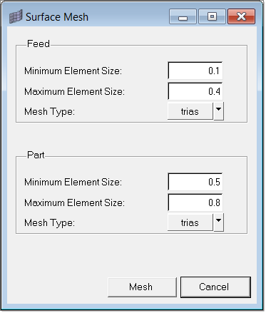
| 13. | Click Mesh to generate the surface mesh. |
| 14. | Click on the checkbox Volume Mesh. The Volume Mesh dialog opens. Specify the Number of Layers as 2 as required in the solid mesh and the First Layer Thickness as 0.3. |
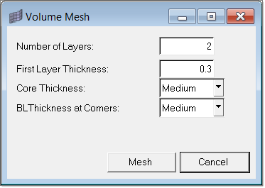
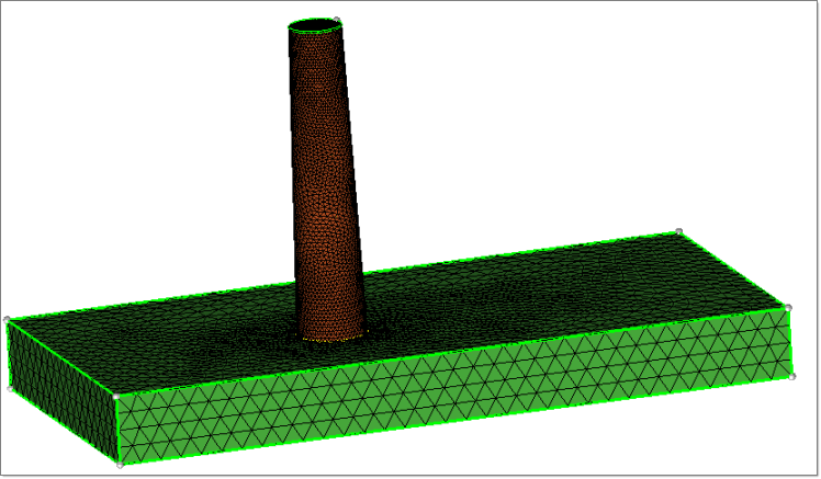
| 15. | Click Mesh to generate the solid mesh. Switch off the collectors part and runner from the Model browser to visualize the solid mesh. Click Close in the Moldex3D Wizard. |
|
| 1. | In the Utility menu, click Create Property Cards |
| 2. | Click Solid Mesh. A panel to select the elements opens. |
| 3. | Select the elements in the collector flow3d_mesh0. Click proceed. The Create/Assign Solid Mesh Properties dialog opens. |
| 4. | Select the option Cold Runner solid mesh from the drop down and click OK. |
| 5. | Repeat steps 3 and 4. This time select flow3d_mesh1 and Cavity (Part) solid mesh. |
| 6. | Click Back to return to the main Utility menu. |
|
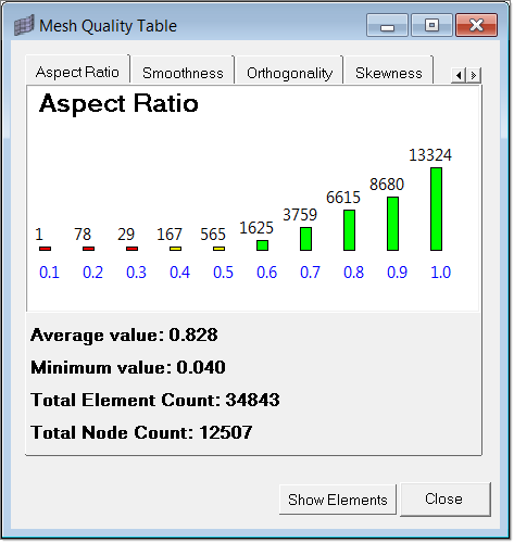
| 1. | Click Diagnostics. The Mesh Quality Table appears showing the quality. |
| 2. | Click on each tab to view the distribution. Click Show Elements to see the elements falling in the range selected. |
|
| 1. | Click Create Property Cards. |
| 2. | Under the BCs header, click Points. A panel to select the node(s) appears. |
| 3. | Select a node on the cold runner from the graphic area as shown below and click proceed. The Create Boundary Condition dialog appears. |
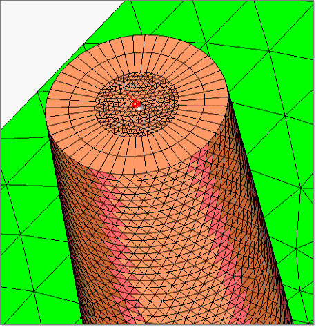
| 4. | Select Melt Entrance for BC type. Click OK. Notice the boundary condition on the node. |
| 5. | Click Back to return to the main Utility menu. |
|
| 1. | Click Export. The Moldex3D MFE Export tab displays. |
| 2. | Specify the file path and name to write the MFE file and click Export. The status of export is shown in the status bar. |
|
| 1. | Load the exported MFE file in the Moldex3D solver. |
|
Return to Moldex3D Tutorials


