In this tutorial, you will learn how to:
| • | Load a HyperMesh file containing solid mesh of the part and the runner |
| • | Mesh the runner using solid map |
| • | Mesh the part using CFD BL mesh |
| • | Assign property card(s) to the part and the runner |
| • | Define melt entrance boundary condition |
| • | Export the model as a Moldex3D MFE file |
The model files for this tutorial are located in the file mfs-1.zip in the subdirectory \HyperMold\Moldex3D\MX_1010. See Accessing Model Files.
To work on this tutorial, it is recommended that you copy this folder to your local hard drive where you store your HyperXtrude data, for example, “C:\Users\Moldex3D\” on a Windows machine. This will enable you to edit and modify these files without affecting the original data. In addition, it is best to keep the data on a local disk attached to the machine to improve the I/O performance of the software.
| 2. | On the Preferences menu, click User Profiles. |
| 3. | In the Application field, select Manufacturing Solutions. |
| 4. | Select HyperMold and Moldex3D/Solid. |
|
| 1. | In the Model browser, right-click on the component runner and select the option Make Current. The component name will become bold. |
| 2. | Click Mesh > Create > 2D AutoMesh. The Automesh panel opens. |
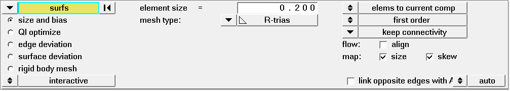
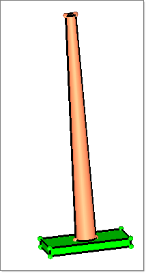
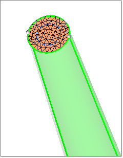
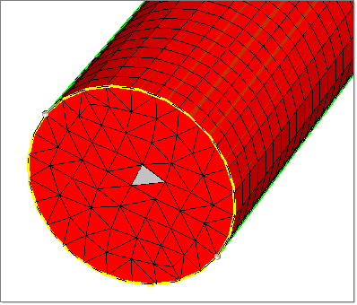
| 3. | Pick the topmost surface of the runner as shown below. Set the mesh type to R-trias. Set the element size to 0.2. |
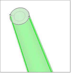
| 4. | Click mesh to generate surface mesh on the top most surface. Click return twice to exit the panel. |
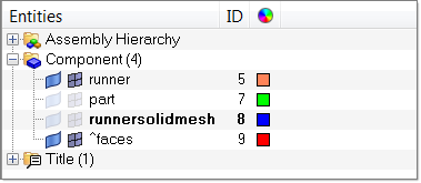
| 5. | In the Model browser, set the component runnersolidmesh as the current collector. |
| 6. | Click solid map in the main menu. The Solid Map panel opens. |
| 7. | Select the one volume subpanel. |
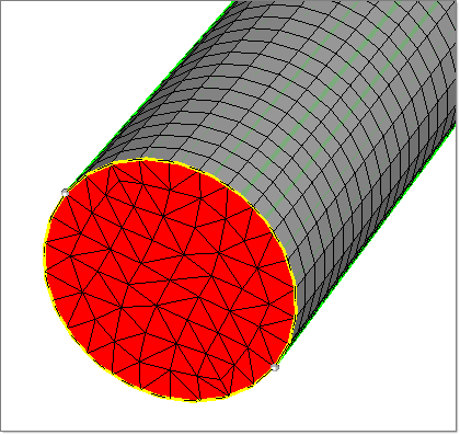
| 8. | With the solid button under the option volume to mesh highlighted, select the runner solid from the graphics area. |
| 9. | Click surfs under the option source hint, and select the top most surface of the runner. |
| 10. | Click the switch for the source shells option, and select R-trias. |
| 11. | Set the switch from elems to solid/surf comp to elems to current comp. |
| 12. | Set the elem size field to 0.5. |
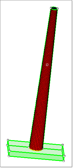
| 13. | Click mesh to generate the solid mesh for the runner. Click return to close the panel. |
| 14. | From the main menu, click faces. |
| 15. | Select the component runnersolidmesh either by picking from the graphics area or by clicking comps and selecting it from the component list. Click find faces to generate the faces, then click return to close the panel. |
The face elements are placed in the component ^faces. Use the Model browser to switch off all other components except ^faces and the runner.
| 16. | From the menu bar, click on Mesh > Delete > Elements. The Delete panel displays. |
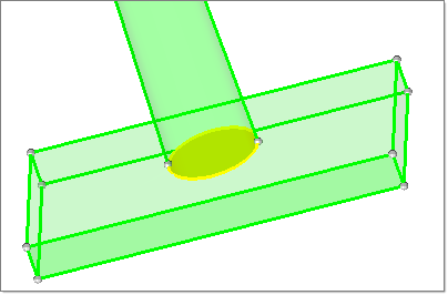
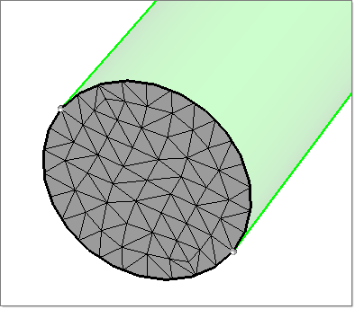
| 17. | Select any element on the bottom most face of the runner as shown below. Then click elems >> by face. |
| 18. | Click elems again and select reverse. |
| 19. | Click delete entity to delete the elements. Click return to exit the panel. |
| 21. | Select the to surface subpanel. |
| 22. | Click on the selector and change it to elems. |
| 23. | For the option along vector, click the toggle button and set it to surface normal. |
| 24. | Click elems >> displayed. |
| 25. | Click surf and pick the bottom most surface of the runner. |
| 26. | Click project to project the face elements. Click return to exit the panel. |
|
| 1. | Switch on the part geometry and mesh from the Model browser by clicking on the icons  and and  next to the component part. Switch off the runner geometry and mesh from the Model browser by clicking on the same icons next to the component runner. next to the component part. Switch off the runner geometry and mesh from the Model browser by clicking on the same icons next to the component runner. |
| 3. | Click elems >> displayed. |
| 4. | Click dest component = and select the component part. |
| 5. | Click move to move the elements to the component part. Click return to close the panel. |
| 6. | In the Model browser, make the part component the current component. |
| 7. | Click Surface Mesh in the Utility menu. The Automesh panel displays. |
| 8. | Select the surface where the runner meets the part as shown below. Click surfs >> reverse to select the remaining surfaces. |
| 9. | Set the element size field to 0.5 and click mesh. Click return twice to exit the panel. |
| 10. | In the Utility menu, click Layered Tet Mesh. |
| 11. | Click Def BL Thickness. A new dialog opens, as show below: |
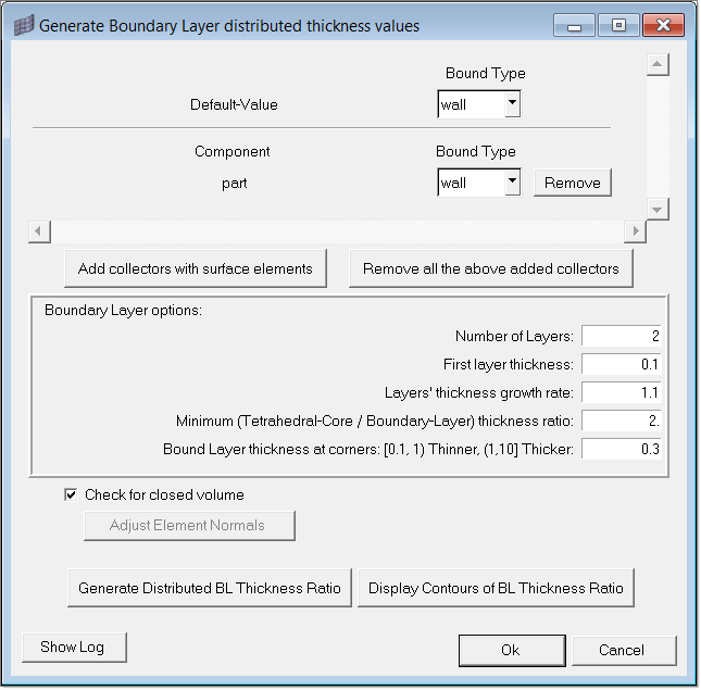
| 12. | Click Add collectors with surface elements. A panel to select components displays. |
| 13. | Select the component part and click proceed. |
| 14. | Set the number of layers field to 2. |
| 15. | Set the first layer thickness field to 0.1. |
| 16. | Click Generate Distributed BL Thickness Ratio to generate distributed BL information. A message appears to confirm the BL information generation. Click OK. |
| 17. | Click Close to close the dialog. |
| 18. | Click CFD Tet Mesh in the same macro page. The CFD Tetramesh panel opens. |
| 19. | In the Boundary selection subpanel, select the component part from the graphics for elements with boundary layer (fixed). |
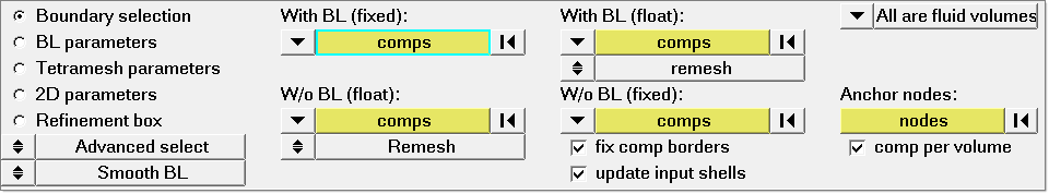
| 20. | In the BL parameters subpanel, set the number of layers field to 2. |
| 21. | Set the first layer thickness field to 0.1 and BL growth rate field to 1.00. |
| 22. | Click mesh to start the CFD BL meshing. CFD BL meshing will take couple of seconds to complete. When finished, click return to exit the panel. |
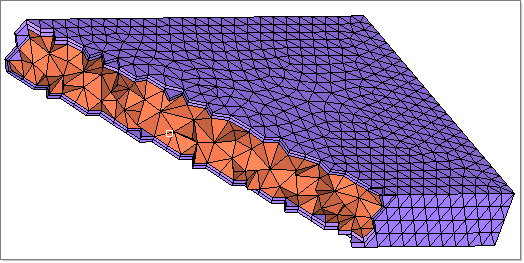
| 23. | The CFD BL mesh for the part is placed in two newly created components CFD_boundary_layer and CFD_tetramesh_core. Switch off the display of the component part to visualize the CFD BL mesh of the part. You can also use the Mask panel to display the newly created mesh. |
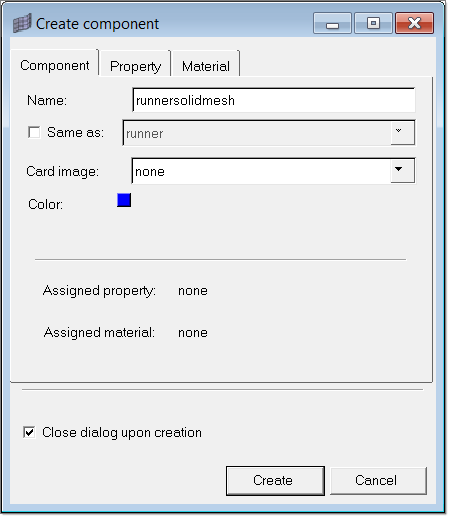
| 24. | In the Model browser, create a new component collector called partsolidmesh. |
| 25. | Click organize and move the elements from the collectors CFD_boundary_layer and CFD_tetramesh_core to the collector partsolidmesh. Now the collectors you created have the solid meshes for the runner and the part. |
| 26. | In the Utility menu, click Back. |
|
| 1. | In the Utility menu, click Create Property Cards under Model Setup. |
| 2. | Click Solid Mesh. A panel to select the elements opens. |
| 3. | Select the elements in the collector runnersolidmesh and click proceed. The Create/Assign Solid Mesh Properties dialog displays. |
| 4. | Select Cold runner solid mesh from the drop-down menu and click OK. |
| 5. | Repeat the steps 3-4. This time select the collector partsolidmesh and select Cavity (Part) solid mesh from the drop-down menu. |
| 6. | Click Back to return to the Utility menu. |
|
| 1. | Click Diagnostics. The Mesh Quality Table displays, showing the quality. Click on each tab to view the distribution. Click Show Elements to see the elements falling in the range selected. |
| 2. | Click Cancel to close the table. |

|
| 1. | Click Create Property Cards. |
| 2. | Under the BCs header, click Points. A panel to select the node(s) appears. |
| 3. | Select a node on the cold runner from the graphic area as shown below and click proceed. The Create Boundary Condition dialog opens. |
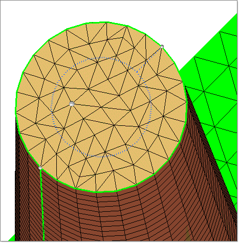
| 4. | Select Melt Entrance for BC type. Click OK. Notice the boundary condition on the node. |
| 5. | Click Back to return to the Utility menu. |
|
| 1. | Click Export. The Moldex3D MFE Export tab is displayed: |
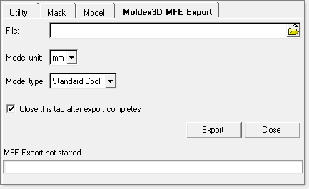
| 2. | Specify the file path and name to write the MSH file and click Export. The status of export is shown in the status bar. |
| 3. | For Model type, keep the default option, Standard Cool. |
Note: The option, Fast Cool, can be applied when the mold base is meshed via surface mesh. For the current model, Fast Cool does not apply.
|
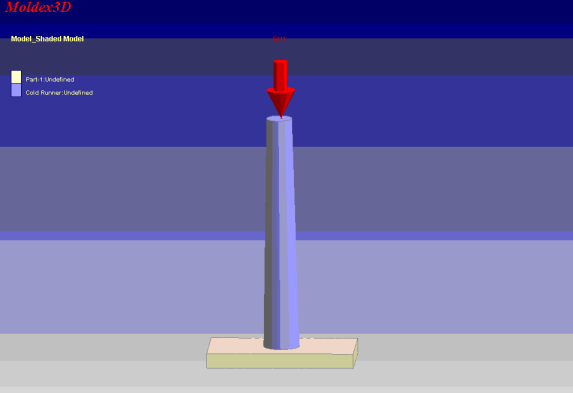
| 1. | Load the exported MSH file in Moldex3D solver. |
| 2. | Solve the model and post-process. |
|
Return to Moldex3D Tutorials