In this tutorial, you will learn how to:
| • | Load a HyperMesh file containing geometries of the part, runner, coolant channel and moldbase |
| • | Mesh the part, runner, coolant channel and the moldbase |
| • | Assign property card to the part and moldbase |
| • | Create the runner system |
| • | Create the coolant channel system |
| • | Inspect mesh quality and thickness contour |
| • | Define melt entrance and coolant entrance/exit boundary conditions |
| • | Export the model as a Moldex3D MSH file |
The model files for this tutorial are located in the file mfs-1.zip in the subdirectory \HyperMold\Moldex3D\MX_0040. See Accessing Model Files.
To work on this tutorial, it is recommended that you copy this folder to your local hard drive where you store your HyperXtrude data, for example, “C:\Users\Moldex3D\” on a Windows machine. This will enable you to edit and modify these files without affecting the original data. In addition, it is best to keep the data on a local disk attached to the machine to improve the I/O performance of the software.
| 2. | On the Preferences menu, click User Profiles. |
| 3. | In the Application field, select Manufacturing Solutions. |
| 4. | Select HyperMold and Moldex3D/Shell. |
|
| 1. | From the File menu, click Open. |
| 2. | Browse to the file MX_0040.hm. |
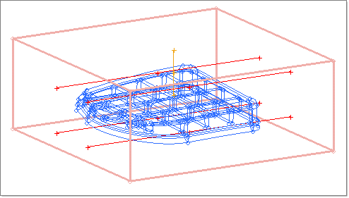
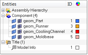
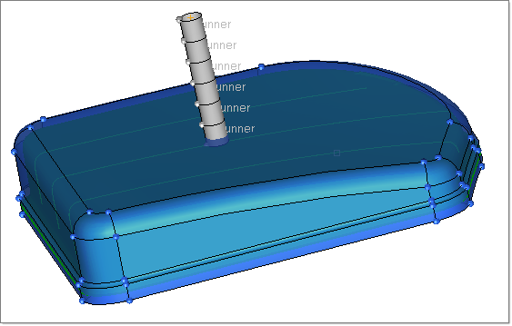
| 4. | Click on the Model tab to view the contents of the file. The part geometry is in the component collector geom_Part. Lines that constitute the runner are in the component geom_Runner and lines that constitute the cooling channel are in the component geom_CoolingChannel. The moldbase geometry is in the component geom_Moldbase. |
|
The following steps outline how the middle surface was created. You do not have to repeat these steps as the model you started with already contains the middle surface.
| 1. | Click Geometry > Create > Midsurfaces > Auto. |
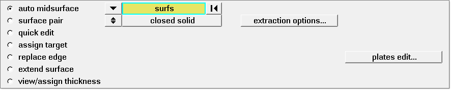
| 2. | Click surfs >> by collector. |
| 3. | Select the collector geom_Part. Click select and click extract. Midsurface extraction takes a couple of seconds. The midsurface is placed in a new collector name Middle Surface. |
| 4. | Click return to exit the panel. |
The created midsurface will have some errors; by using surface edit and Autocleanup functions, these errors were corrected. These steps are not presented here as they will distract the focus of this tutorial. Hence, the corrected midsurface was included in the model provided.
|
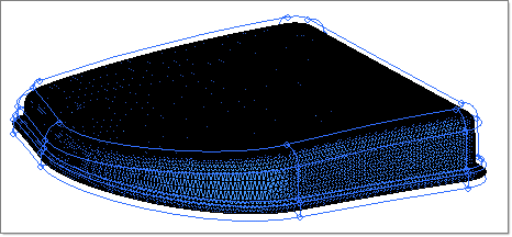
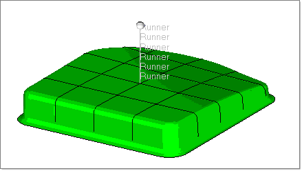
| 1. | From the Model browser, right-click on the component geom_Part and select Make Current. Right-click again and select Isolate. Click the  icon to make sure the component displays completely. icon to make sure the component displays completely. |
| 2. | To generate surface mesh on the part, click Mesh > Create > 2D Automesh. The Automesh panel opens. |
| 3. | Click surfs >> by collector and pick Middle Surface. Click select. |
| 4. | Set the element size field to 1.0. |
| 5. | Set the mesh type field to trias. |
| 6. | Set the switch to elems to current comp. |
| 7. | Click mesh to generate the mesh. |
| 8. | Click return twice to exit the panel. |
| 9. | In the Model browser, set the collector geom_Moldbase as the current collector and isolate it in the view. |
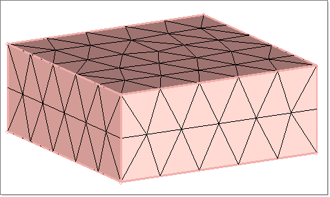
| 10. | Click Mesh > Create > 2D Automesh again. Click surfs and select the surfaces in the collector geom_Moldbase. |
| 11. | Set the element size to 30.0 and the mesh type to trias. |
| 13. | Click return twice to exit the panel. |
| 14. | From the Model browser, set the collector geom_Runner as the current collector. Show both the geom_Runner and geom_Part components in the view. |
| 15. | In the Utility menu, click Runner System Mesh to open the Line Mesh panel. |
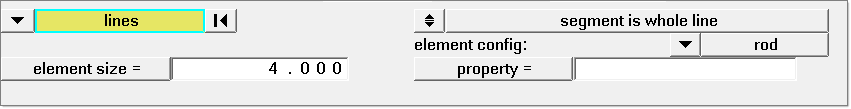
| 16. | Click lines and select the collector geom_Runner. |
| 17. | Set the element size field to 5. Click mesh in the Line Mesh panel. Click return twice to exit the panel. |
| 18. | From the Model browser, set the collector geom_CoolingChannel as the current collector and display it. From the Utility menu, click Coolant System Mesh to open the Line Mesh panel. |
| 19. | Pick the lines in the collector geom_CoolingChannel. Set the element size to 30.0 and click mesh. |
| 20. | Click return twice to close the panel. |
|
| 1. | In the Utility menu, click Create Property Cards under the Model Setup header. A new tab opens. |
| 2. | Click on Assign Thickness. The Extract/Assign Cavity Thickness dialog appears. |
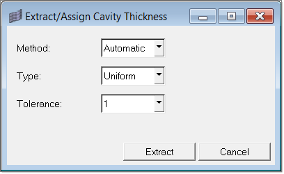
| 3. | Keep the default values and click Extract. A panel to select the surface(s) that constitute the part will appear. |
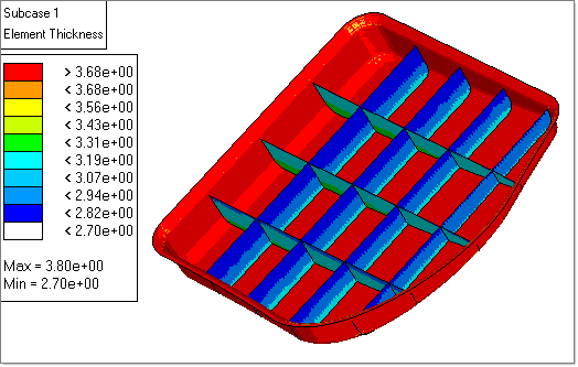
| 4. | Select the surfaces in the collector Middle Surface. Click proceed. |
Thickness information is retrieved from the nodes of the part mesh and is stored in property cards(s). At the end of thickness extraction, a thickness contour for the part is plotted.
| 5. | Click Shell Mesh again. A panel to select elements opens. |
| 6. | Select the elements in the collector geom_Moldbase and click proceed. The Create/Assign Surface Mesh Properties dialog opens. |
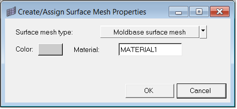
| 7. | Retain the default options. Click OK to complete the property card assignment for Moldbase surface mesh. |
| 8. | Click return to close the panel. |
|
| 1. | In the Model browser, right-click on geom_Runner and make it the current component. |
| 2. | In the Utility menu, click Create Runner button. It opens a new dialog. |
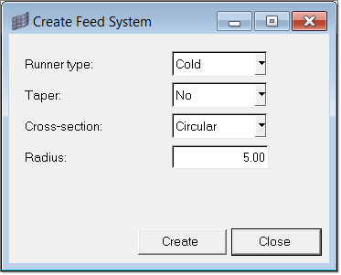
| 3. | Set the Radius as 5.0 and click Create. A panel to select the runner elements opens. |
| 4. | Select the elements in the collector geom_Runner. Click proceed. |
|
| 1. | In the Model browser, right-click on geom_CoolingChannel and make it the current component and display it. |
| 2. | Click Coolant Channel. A panel to select the coolant channel elements opens. Select the elements in the collector geom_CoolingChannel. Click proceed. The Create Coolant Channel dialog opens. |
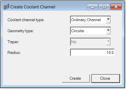
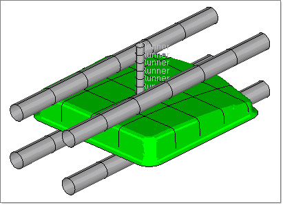
| 3. | Set the options as shown in the image above and click Create. Surface generation for coolant channel visualization takes couple of seconds to complete. |
| 4. | In the Utility menu, click Back to return to the main Utility menu. |
|
| 1. | Click Diagnostics. A new macro page opens. |
| 2. | Click Show Quality Table. The mesh quality plot displays. |
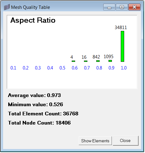
| 3. | Based on the plot, you can conclude that the mesh is of good quality and can be exported. Click Cancel to close the dialog. |
| 4. | Click Back to return to the main Utility menu, and click return to close the panel. |
|
| 1. | Click Create Property Cards. It opens a new macro page. |
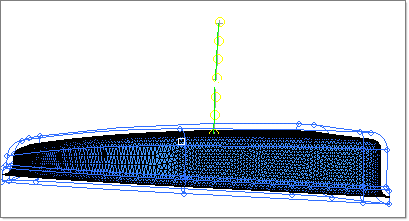
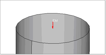
| 2. | Click on the BCs macro button. A panel to select the node(s) displays. Select the top most node of the runner as shown below. Click proceed. |
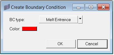
| 3. | The Create Boundary Condition dialog displays. Click OK to complete the Melt Entrance Boundary condition creation. |
|
| 1. | Click Create Property Cards. |
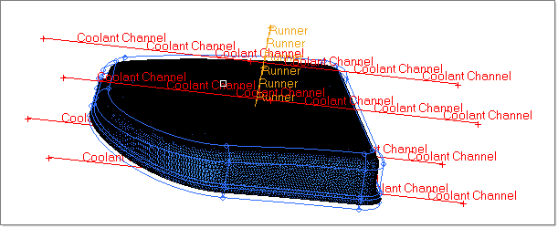
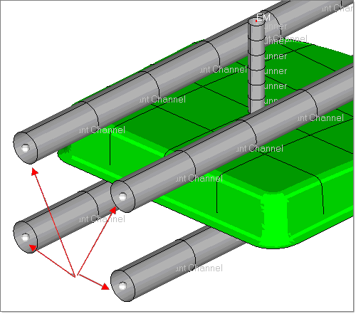
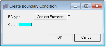
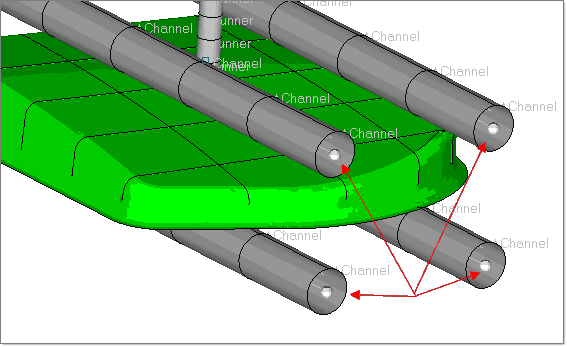
| 2. | Click BCs. A panel to select the node(s) displays. Select the four left extremes nodes of the coolant channel as shown below and click proceed. The Create Boundary Condition dialog displays. |
| 3. | Click the BC type switch and change it to Coolant Entrance. Click OK to create the coolant entrance BC. |
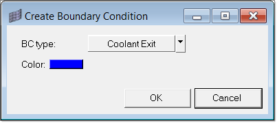
| 4. | Click BCs again and pick the nodes on the other side for coolant exit. |
| 5. | In the BC panel, select Coolant Exit and click OK to create the exit BC. |
|
| 1. | Click edges in the main menu. The Edges panel displays. |
| 2. | If necessary, click the switch from comps to elems. |
| 3. | Click elems >> all. Click preview equivalence to find coincident nodes. In this model, you will find one coincident node between the runner mesh and the part mesh. |
| 4. | Click equivalence to remove the coincident node. |
| 5. | Click return to close the panel, and click Back to return to the main Utility menu. |
|
| 1. | Click Export. The Moldex3D MSH Export tab displays. |
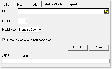
| 2. | Specify the file path and name to write the MSH file and click Export. The status of export is shown in the status bar. |
|
Return to Moldex3D Tutorials


