In this tutorial, you will learn how to create a finite element mesh from a 3D CAD file.
The model files for this tutorial are located in the file mfs-1.zip in the subdirectory \hx\MetalExtrusion\HX_1022. See Accessing Model Files
To work on this tutorial, it is recommended that you copy this folder to your local hard drive where you store your HyperXtrude data, for example, “C:\Users\HyperXtrude\” on a Windows machine. This will enable you to edit and modify these files without affecting the original data. In addition, it is best to keep the data on a local disk attached to the machine to improve the I/O performance of the software.
|
| 1. | Select Start Menu > All Programs > Altair Hyperworks > Manufacturing Solutions > HyperXtrude to launch the HyperXtrude User Interface. The User Profiles window appears with Manufacturing Solutions as the default application. The HyperXtrude radio button will be selected by default. |
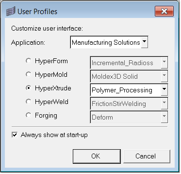
| 2. | Select Polymer_Processing from the drop down menu of HyperXtrude. |
|
| 1. | From the File menu, click Open. |
| 2. | Browse to the file HX_1022.hm. |
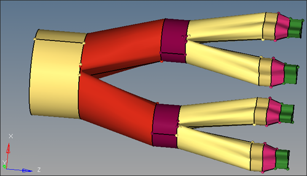
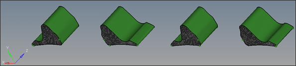
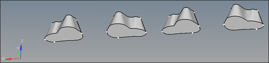
| 4. | Click the Shaded Geometry and Surface Edges icon  to view the model as displayed below: to view the model as displayed below: |
|
| 1. | Click on the Model tab to display the Model browser. |
| 2. | Right-click in the white space and select Create > Component. The Create Component window opens. |
| 3. | Enter the component name as Profile3D and select different a color. |
| 4. | Click Create to create the component. |
| 5. | Repeat Step 2 through 4 to create the components Land3D, Manifold0_3D, Manifold1_3D, Manifold2_3D, Manifold3_3D, Manifold4_3D and Manifold5_3D. |
|
| 1. | In the Model browser, expand the Component folder, right-click on the Land component and select Isolate. |
| 2. | Right-click on Land again and select Make Current. |
| 3. | Select automesh from the main menu. |
| 4. | With the yellow surfs button active, select the four yellow surfaces. |
| 5. | Set the mesh type to trias and enter the element size as 0.5. |
| 6. | Toggle the element location to elems to current comp. |
| 7. | Click mesh to create the surface mesh. |
| 8. | Click return twice to close the panels. |
| 9. | In the Model browser right-click on Land3D and then click on Make Current to set Land3D as the current component collector. Right-click again and select Show. |
| 10. | Select the Drag panel from the main menu. |
| 11. | Select the drag elems subpanel and toggle to Z-axis for the drag direction. |
| 12. | Click elems >> displayed. |
| 13. | In the distance = field, enter 12.7 |
| 14. | In the on drag = field, enter the number of elements as 15. |
| 15. | Click drag+ to create 3D elements in the land region. |
| 16. | Click return to close the panel. |
|
| 1. | Right-click on Profile3D and select Make Current. Right click again and select Show. |
| 2. | In the main menu, click faces. |
| 3. | Click comps and select Land3D. This selects all the elements in the Land3D component. |
| 4. | Click on find faces. This will create 2D elements enclosing the 3D elements. |
| 5. | Click return to close the panel. |
| 6. | Using the Model browser, hide the Land3D component. |
| 7. | Select the Drag panel from the main menu. |
| 8. | Select the drag elems subpanel. |
| 9. | Click "v" on the keyboard to open the user views dialog and select the iso 1 view. |
| 10. | Select one element on the top of each of the four surfaces. |
| 11. | Click elems >> by face. |
| 12. | Set the drag direction to Z-axis. |
| 13. | In the distance= field, enter 40. |
| 14. | In the on drag = field, enter the number of elements as 10. |
| 15. | Make sure that bias style is set to linear. Enter 3 for bias intensity. |
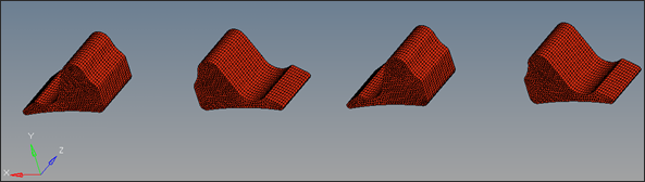
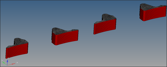
| 16. | Click drag+ to create 3D elements in the profile region. |
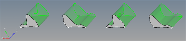
| 17. | Click return to close the panel. |
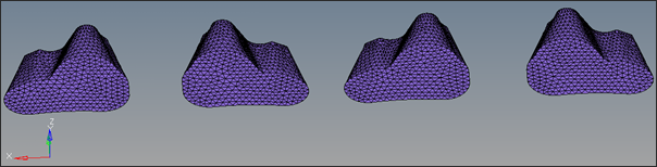
Two of the four sections are shown
|
| 1. | In the Model browser, right-click on the Manifold5 component and select Isolate. |
| 2. | Right-click on Manifold5 and select Make Current. Right-click again and select Show. |
| 3. | Select the Tetramesh panel from the main menu. |
| 4. | Select the Volume tetra subpanel for meshing. |
| 5. | Click solids >> displayed. |
| 6. | Set the element size to 1.5. |
| 7. | Click mesh to create tetramesh for Manifold5_3D component. |
| 8. | Click return to close the panel. |
| 9. | Follow the steps 1 - 8 above to create tetra elements for Manifold4_3D, Manifold3_3D, Manifold2_3D, Manifold1_3D and Manifold0_3D by using the following components and element sizes respectively |
Meshed Component
|
Component
|
Element Size
|
Manifold4 3D
|
Manifold4
|
1.5mm
|
Manifold3 3D
|
Manifold3
|
3.0mm
|
Manifold2 3D
|
Manifold2
|
5.0mm
|
Manifold1 3D
|
Manifold1
|
6.0mm
|
Manifold0 3D
|
Manifold0
|
7.0mm
|
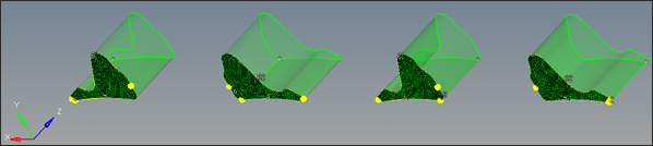
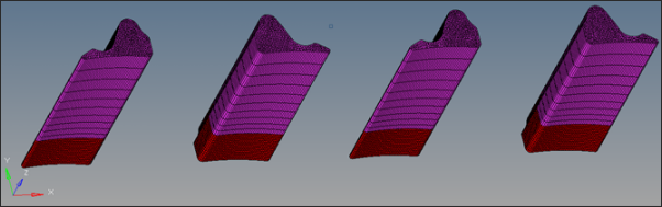
| 10. | Once meshing is done, right click on faces component in the Model browser and select Delete. |
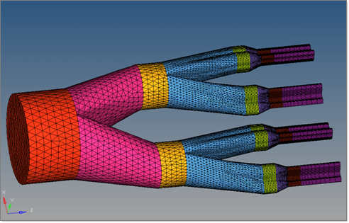
| 12. | Turn the display on for all the 3D components in the Model browser. You will see the model as shown below. |
|
Return to Polymer Processing Tutorials


