Plate dies are used for profile extrusion and are created by assembling a series of plates that form the negative volume through which the polymer melt flows to form the final shape. Since the negative volume is formed by a series of plates bolted together, it is possible to automate the meshing and the model setup process for these dies. The purpose of the Plate Meshing Wizard is to achieve this automation.
The model files for this tutorial are located in the file mfs-1.zip in the subdirectory \hx\MetalExtrusion\HX_1151. See Accessing Model Files
To work on this tutorial, it is recommended that you copy this folder to your local hard drive where you store your HyperXtrude data, for example, “C:\Users\HyperXtrude\” on a Windows machine. This will enable you to edit and modify these files without affecting the original data. In addition, it is best to keep the data on a local disk attached to the machine to improve the I/O performance of the software.
| • | Tutorial file - you will start from this file: |
- HX_1151.hm
| • | Completed files provided for reference: |
- HX_1151_completed.hm
|
| 1. | Select Start Menu > All Programs > Altair Hyperworks > Manufacturing Solutions > HyperXtrude to launch the HyperXtrude User Interface. The User Profiles window appears with Manufacturing Solutions as the default application. The HyperXtrude radio button is also selected by default. |
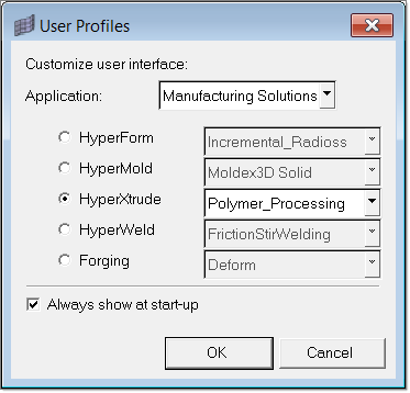
| 2. | Select Polymer_Processing from the drop down menu of HyperXtrude. |
|
| 1. | From the File menu, click Open. |
| 2. | Browse to the file HX_1151.hm. This file contains the solid geometry and default unit selections. |
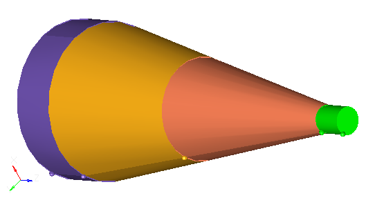
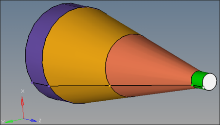
| 4. | Inspect the model. There are four components in the model, named Manifold0, Manifold1, Manifold2, and Manifold3. |
Manifold0 corresponds to the inlet manifold, and Manifold3 corresponds to the land. There is no solid corresponding to the profile and it is automatically created.
|
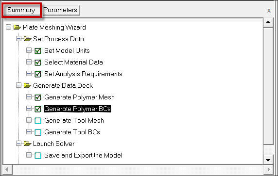
| 1. | From the Utility menu, click Plate Meshing Wizard. The Project browser dialog opens with the root directory already set. |
| 2. | Right-click and select New Project. |
| 3. | Enter the name HX_1151 and press ENTER. (Or you can choose any sub folder of the root directory to create this new project). |
| Note: | If you have not set up the root directory, you can configure the settings by right clicking in the dialog, and selecting Edit Settings. The steps to configure the Project browser settings and set up root directory are explained in tutorial HX_0004. |
| 4. | Right click on the project name and select Select Model file. Browse to choose the file HX_1151.hm. This opens the access to set up all the process data. |
|
| 1. | Click Set Model Units. Set the Unit System set to Metric. |
You can mix SI and British units. HyperXtrude will convert everything to non-dimensional form when computing the solution.
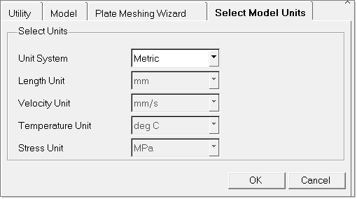
| 2. | Click OK to close the dialog. |
|
| 1. | Click Select Material Data. This opens the Select and Assign Material from Database window. |
| 2. | Under System materials, expand Polymers, then expand PVC. |
| 3. | Select PVC_Generic and click Add to add the material to the Selected materials column. |
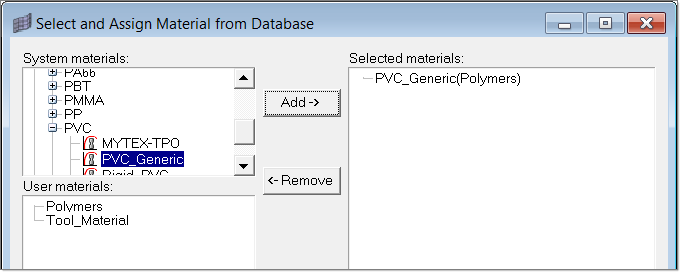
| 4. | Click Close to close the Select and Assign Material from Database window. |
|
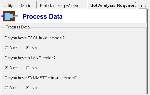
| 1. | Click Set Analysis Requirements. A series of options are shown to specify the model information. |
| 2. | Refer to the image below to set the first options: |
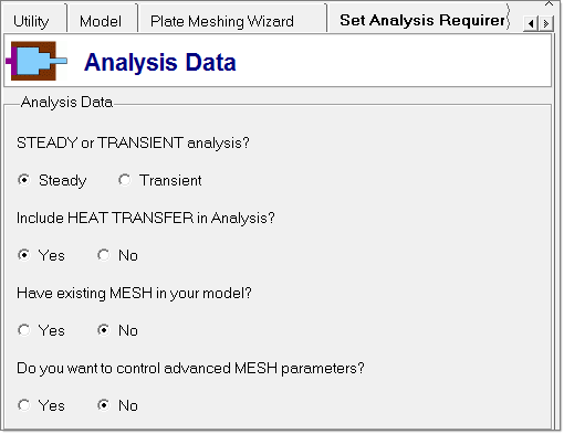
| 3. | Click Next and select the options shown in the image below. You are solving this model under steady-state and are considering heat transfer in the analysis. |
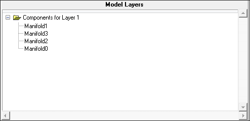
| 4. | Click Next to open the component selection window. Select all the components by holding the CTRL key. With all of them still selected, right click and select Add to Layer 1 components as shown below. |
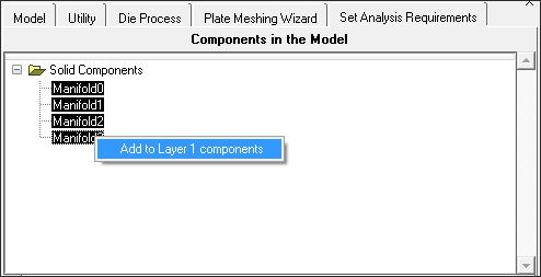
Notice that all the components are added to Layer 1. All the components appear in the Model Layers window as shown below:
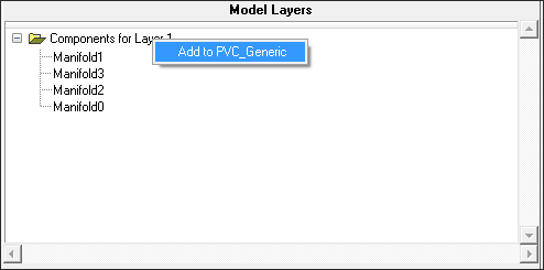
| 5. | Right click on Components for Layer 1 and select Add to PVC_Generic as shown below: |
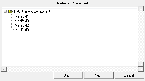
Notice that all the components are added under PVC_Generic Componets in the Materials Selected window.
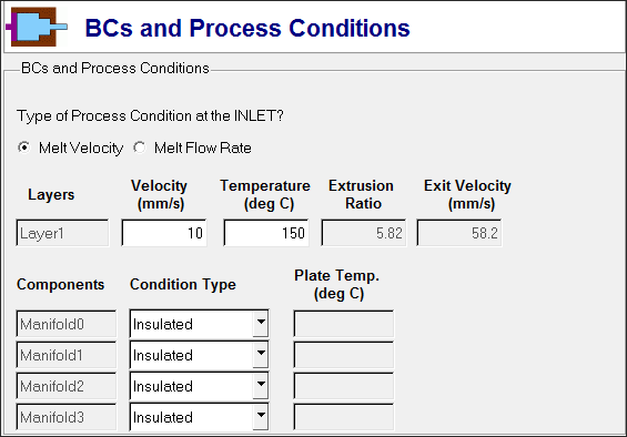
| 6. | Click Next to open the Set Analysis Requirements tab. |
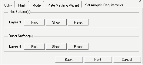
| 7. | Under Inlet Surface(s), for Layer 1, click on Pick and select the inlet surface in the graphics window. |

| 8. | Click proceed. After the successful selection, the Pick button turns green. |
| 9. | Under Outlet surface(s), for Layer 1, click Pick, select the outlet surface, and click proceed. After the successful selection, the Pick button turns green. |
| 11. | Accept the default settings in the window below and click OK to proceed for meshing. |
|
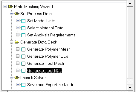
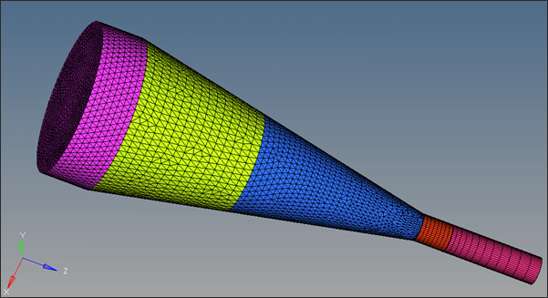
| 1. | Click Generate Polymer Mesh. The Plate Meshing Wizard automatically detects and renames the component collectors for the extrusion components. |
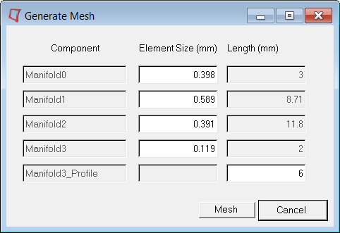
| 2. | Click Mesh, and then click OK. This creates a tetrahedral mesh in all components except the Land and Profile regions. In these regions, it creates prism elements. |
|
| 1. | Click on Generate Polymer BCs. |
This step will create boundary conditions. You can observe that all the created BCs are shown under Components in the Model browser. Depending on the size of the model, this step could take anywhere from a few seconds to a few minutes.
| 2. | Click on Summary to inspect the model summary. |
| 3. | Click on the Element Statistics tab. |
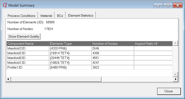
| 4. | Click Close to close the Model Summary dialog. |
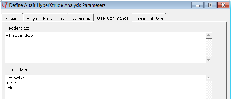
| 5. | Click on Parameters. Click on User Commands, and set the Footer data as shown below: |
|
| 1. | Click Save and Export the Model in the Plate Meshing Wizard. It will open the following dialog. Choose the correct location and name for Project file name. |
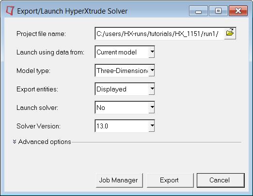
| 2. | Click Export to export the model. If you set the Launch solver field to interactive, you can solve the model interactively. On the other hand, if you set the value to No, you should have the commands solve and exit in the user commands are to submit the job on the remote machine. |
This concludes the tutorial. For your reference, the tutorial directory includes the completed model file.You can learn more about post-processing in the post-processing section of the tutorials.
|
Return to Polymer Processing Tutorials


