This tutorial explains how to do a profile deformation analysis for polymer extrusion. The procedure involved is similar to that of metal extrusion. The key to the analysis is to define the surfaces of the exiting product as a free surface. The product exiting the die is called extrudate and it will deform due to imbalances in the velocity field. Often, these imbalances caused by the normal stress effect will lead to extrudate swell. However, viscoelasticity is not considered in this exercise. Hence, the velocity imbalances arise from the die design. This analysis is not complete by itself, as most polymer extrusion dies have a calibration die to correct the shape of the product and also to cool it to a stable temperature. This analysis does not include the calibration phase.
The model files for this tutorial are located in the file mfs-1.zip in the subdirectory \hx\MetalExtrusion\HX_1152. See Accessing Model Files.
To work on this tutorial, it is recommended that you copy this folder to your local hard drive where you store your HyperXtrude data, for example, “C:\Users\HyperXtrude\” on a Windows machine. This will enable you to edit and modify these files without affecting the original data. In addition, it is best to keep the data on a local disk attached to the machine to improve the I/O performance of the software.
- HX_1152.hm
| • | Completed files provided for reference |
- HX_1152_completed.hm
|
| 1. | Select Start Menu > All Programs > Altair Hyperworks > Manufacturing Solutions > HyperXtrude to launch the HyperXtrude User Interface. The User Profiles window appears with Manufacturing Solutions as the default application and the HyperXtrude radio button selected. |
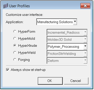
| 2. | Select Polymer_Processing from the drop down menu of HyperXtrude. |
| 4. | Browse to the file HX_1152.hm. |
| 5. | Click Open to open the file. |
The loaded model contains the completed mesh, which is in the collectors Land3D, Profile3D, and Transition3D.
| 6. | On the Utility menu, click the Select Units macro. |
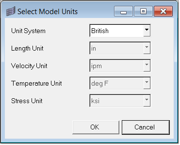
| 7. | Change the Unit System field to British and click OK. |
HyperXtrude allows you to work with mixed sets of units - that is, you can mix SI and British units. Selecting the model units should be the first step after loading the model.
| 8. | A confirmation dialog asks if you wish to also apply the unit conversion to boundary data; click OK. |
|
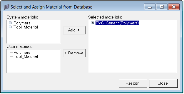
| 1. | On the Utility menu, click the Material Data macro. |
The Select and Assign Material from Database window displays. In this dialog, you will see that PVC_Generic is loaded and assigned to all 3D elements. Since this model is 3D, there is no need to assign material to components that have only 2D elements. It is also important that you do not have components with both 2D and 3D elements. It will cause problems.
|
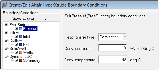
| 1. | On the Utility menu, click the Create/Edit BC macro. |
| 2. | Inspect the boundary data. The model imported is complete with boundary conditions. To inspect the data, look at the parameters and the BC surface it is assigned to it. |
The key BC parameters in this model are in Inflow; velocity in extrusion direction is 0.1 mm/s and inlet temperature is 200o C. All the walls are insulated and the friction condition is stick.
Free surface BC has only heat transfer related parameters. In this example, heat transfer is set to convection conditions.
|
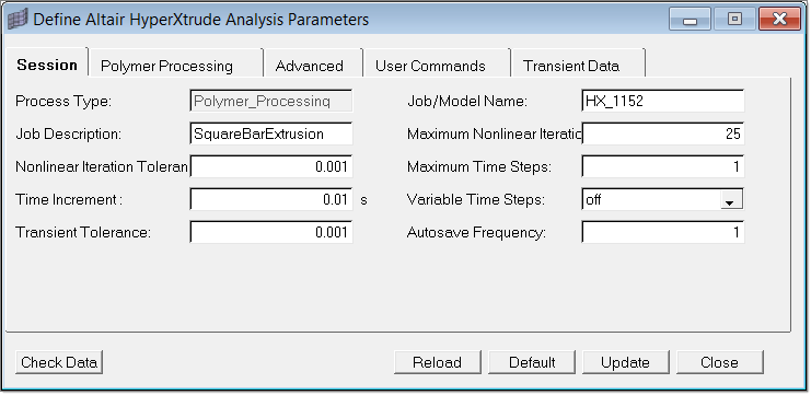
| 1. | On the Utility menu, click the Parameters macro. |
| 2. | Go to the Session tab and set the following parameters: |
| • | Set the Job/Model Name to HX_1152 |
| • | Set the Job Description to SquareBarExtrusion |
| 3. | Click Update to save the data. |
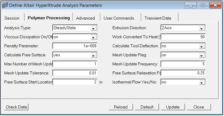
| 4. | Go to the Polymer Processing tab and set the following parameters: |
| • | Set Calculate Free Surface to yes |
| • | Set Mesh Update Flag to on |
| • | Set Max Number of Mesh Updates to 1 |
| • | Set Free Surface Start Location to 2.0, as the z location of free surface start is 2.0. |
| 5. | The remaining parameters use the default value. |
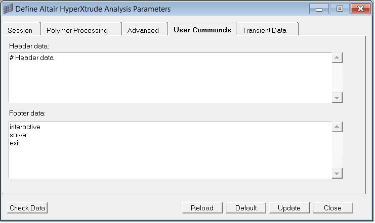
| 6. | Click on the User Commands tab to set the footer data. This will help you invoke the solver in both interactive and batch mode. |
| 7. | Click Update to save the data and then close the window. |
You have successfully completed setting up the data for the run and you can launch the solver. For your reference, the tutorial directory has the completed model.
|
| 1. | On the Utility menu, click Export/Launch Solver. |
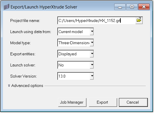
| 2. | In the Project file name field, type HX_1152.grf and two files will generate with the names HX_1152.grf and HX_1152.hx. |
| 3. | Click on Export to start the solver. Since the setting for this is Interactive, the solver will be launched interactively. |
Alternatively, you can set the Launch solver field to No, and submit the job on e-compute.
|
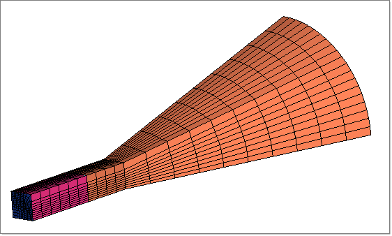
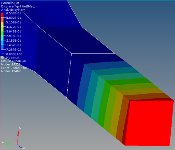
Post-processing is done using HyperView and HyperXtrude automatically writes a full H3D file containing all the results. You can visually inspect the deformation in HyperView by loading the H3D file. The image below shows the displacement contour and the displacement (scaled up by a factor of 4).
|
Analysis of a profile die with free surface deformation was presented in this tutorial. In this particular analysis, you used only one mesh update. Since the deformations are small, you can increase the number of mesh updates to five and see if the deformations converge to the final value. In general, if the first updated deformation is very large, subsequent steps will distort the mesh to an extent that a good solution may not be possible.
|
Return to Polymer Processing Tutorials


