HyperMesh has several functions that require definition of a volume, such as creating tetrahedral and hexahedral meshes. This can be done either surfaces that enclose the volume, or with solid geometry entities. Working with solids provides a couple of advantages over surfaces. Selecting the volume for the function requires only a single click because solids represent the volume with a single entity, as opposed to surfaces. Solids that are topologically connected to each other also allow the functions being used to recognize the connection. Creating mesh in these cases allows mesh in adjacent volumes to automatically have proper connectivity.
In this tutorial, you will learn:
| • | What does 3D topology look like? |
Solids are geometric entities that define a three-dimensional volume. Geometric entities are defined as follows:
| • | Point: 0 dimensional; has only x, y, and z coordinates |
| • | Line: 1-dimensional; has length, can be curved through 3-dimensional space |
| • | Surface: 2-dimensional; has an area |
| • | Solid: 3-dimensional; has a volume |
The model files for this tutorial are located in the file mfs-1.zip in the subdirectory \hx\MetalExtrusion\HX_1003. See Accessing Model Files.
To work on this tutorial, it is recommended that you copy this folder to your local hard drive where you store your HyperXtrude data, for example, “C:\Users\HyperXtrude\” on a Windows machine. This will enable you to edit and modify these files without affecting the original data. In addition, it is best to keep the data on a local disk attached to the machine to improve the I/O performance of the software.
|
| 1. | From the File menu, click Open. |
| 2. | Browse to the file HX_1003.hm. |
|
| 1. | Click Geometry > Create > Solids > Bounding Surfaces. |
| 2. | Verify that the auto select solid surfaces option is checked ON. |
| 3. | Click the yellow surfs button and select one surface on the part. All of the surfaces should automatically be selected. |
| 4. | Click Create to create the solid. The message bar indicates that a solid has been created. The solids are identified by thicker lines than surfaces. |
| 5. | Click return to go back to the main menu. |
| 6. | Repeat steps 1 - 5 to create solids for manifold2 through manifold6. |
|
| 1. | Click Geometry > Edit > Solids > Boolean. |
| 2. | Select the operation type: as simple (combine all). |
| 3. | Click on the solids button next to A: and select manifold0. |
| 4. | Click on the solids button next to B: and select manifold1. |
| 5. | Select {A-B} (cut A with B) as the option under Operation:. |
| 6. | Click calculate. This will create a shared surface (yellow in color) between manifold0 and manifold1. This shared surface will ensure connectivity of nodes during meshing. |
| 7. | Repeat steps 1 - 7 to create a shared surface between the remaining manifolds. |
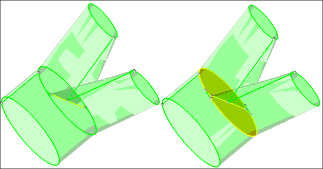
The above figure shows manifold0 and manifold1 before and after the creation of the shared surface.
|
| 1. | Display only the solids in manifold3. |
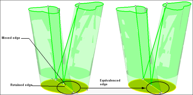
| 2. | Click Geometry > Edit > Surface Edges > Replace. |
| 3. | Select the edges to retain and the edge to move as shown in the image below. |
|
Return to Polymer Processing Tutorials


