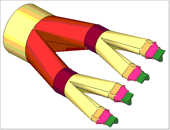
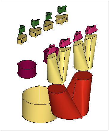
In this tutorial, you will learn about preparing the geometry for meshing. This process involves organizing, editing, and creating missing surfaces to make the model an enclosed volume. The enclosed volume of surfaces is used to create solids. The solids can then be connected to each other by creating the shared surfaces. These connected solids can be meshed either manually or using Plate Meshing Wizard inside the Polymer Extrusion template.
Geometry cleanup is done to achieve the following:
| • | Correct any errors in the geometry from import |
| • | Create the simplified part needed for the analysis |
| • | Ensure proper connectivity of mesh |
| • | Obtain a desirable mesh pattern and quality |
The model files for this tutorial are located in the file mfs-1.zip in the subdirectory \hx\MetalExtrusion\HX_1001. See Accessing Model Files.
To work on this tutorial, it is recommended that you copy this folder to your local hard drive where you store your HyperXtrude data, for example, “C:\Users\HyperXtrude\” on a Windows machine. This will enable you to edit and modify these files without affecting the original data. In addition, it is best to keep the data on a local disk attached to the machine to improve the I/O performance of the software.
|
| 1. | Select Start Menu > All Programs > Altair Hyperworks > Manufacturing Solutions > HyperXtrude to launch the HyperXtrude User Interface. The User Profiles window appears with Manufacturing Solutions as the default application. The HyperXtrude radio button is also selected by default. |
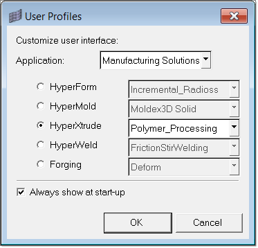
| 2. | Select Polymer_Processing from the HyperXtrude drop-down menu. |
|
| 1. | Observe where the model has incorrect connectivity and missing or duplicate surfaces. |
| 2. | From the main menu, click edge edit. |
| 3. | Note that the surface edges are now colored according to their topology status. This occurs because the Geometry Color option  is set to Auto. is set to Auto. |
| 4. | Click the Wireframe Geometry icon  and the Shaded Geometry & Surface Edges and the Shaded Geometry & Surface Edges  icon to explore the different display modes. icon to explore the different display modes. |
| 5. | The toolbar contains icons that control the display of the surfaces and surface edges. Surfaces can be shaded with or without edges, or wireframe. Click the icons to access the drop down menu for additional options. Place your mouse over the cursor to view a description of the button’s functionality. |
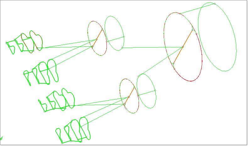
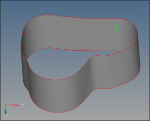
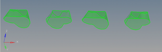
| 6. | Set the display mode back to Wireframe Geometry . The figure below shows all the edges displayed according to their topology. |
Note: In Topology color mode, each color represents different topological mode:
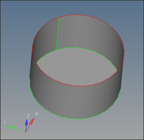
| • | Free edge (red): The edge is owned by one surface. On a clean model, free edges appear only along the outer perimeter of the part and internal holes. Free edges that appear between two adjacent surfaces indicate the existence of a gap between the two surfaces. |
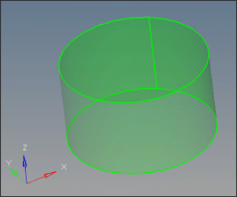
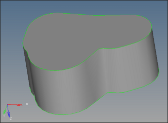
| • | Shared edge (green): The edge is owned by two adjacent surfaces. When the edges between two adjacent surfaces are shared (green), there is no gap or overlap between the two surfaces, and they are geometrically continuous. The automesher always places seed nodes along their length and will produce a continuous mesh without any gaps along that edge. The automesher will not construct any individual elements that cross over a shared edge. |
| • | Suppressed edge (blue): The edge is owned and shared by two adjacent surfaces but it is ignored by the automesher. They are blue dotted lines by default. Like a shared edge, a suppressed edge indicates geometric continuity between two surfaces but, unlike a shared edge, the automesher will mesh across a suppressed edge as if it were not even there. The automesher does not place seed nodes along their length and, consequently, individual elements will span across it. By suppressing undesirable edges you are effectively combining surfaces into larger logical meshable regions. |
| • | Non-manifold edge (yellow): The edge is owned by three or more surfaces. They typically occur at "T" intersections between surfaces or when 2 or more duplicate surfaces exist. The automesher always places seed nodes along their length and will produce a continuous mesh without any gaps along that edge. The automesher will not construct any individual elements that cross over a nonmanifold edge. These edges cannot be suppressed and can sometimes be indication for duplicated geometry. |
| 7. | Click the Visualization icon  and select the Topology icon and select the Topology icon  . . |
Visualization controls the display of the surfaces and surface edges. Surfaces can be shaded or wireframe. The check boxes within this menu turn the display of the different edge types and fixed points (surface vertices) on or off.
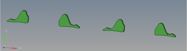
| 8. | Clear all the check boxes except the Free check box. Now only the free edges should be displayed. |
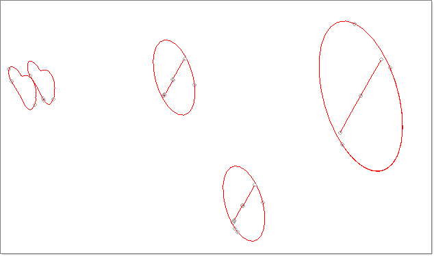
| 9. | Observe the free edges and make a mental note of where they are. The free (red) edges show where there is incorrect connectivity or gaps. |
| 10. | Note the locations where there are closed loops of free edges. These are locations that probably have missing surfaces or are not equivalenced. |
| 11. | Rotate, zoom and pan to locate any errors in the geometry. |
| 12. | Make a mental note of the areas to be worked on. |
| 13. | Click return to close the panel. |
|
| 1. | In the Model browser, expand the Components folder. |
| 2. | Right-click on the component lvl1 and select Rename. |
| 3. | Enter the new name as Manifold0. |
| 4. | Repeat steps 2 and 3 to rename the component as follows: |
| Note: | Use the mesh and surface icons next to the component names to control the display. Click them to turn the display on and off. |
| 5. | Right-click again on Manifold0 and select Make Current. This sets the Manifold0 component as the current component collector. Any newly created surfaces will be put into this collector. |
|
| 1. | Click on Isometric View icon  on the tool bar. on the tool bar. |
| 2. | Click on translate on main menu. |
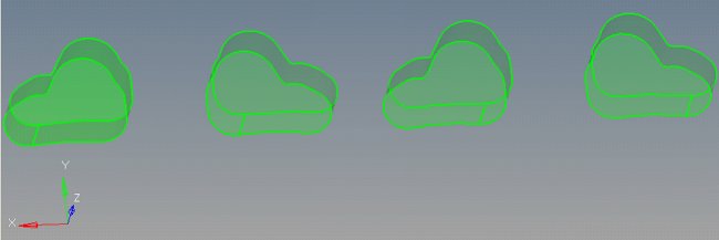
| 3. | Change the entity selector to comps. Change the direction to y-axis and magnitude to 100.00. Select collectors manifold0, Manifold2, Manifold4, Manifold6 and click translate+. |
| 5. | In the Model browser, right click on Components and select Hide. |
| 6. | Right click on Manifold0 and select Show. Right click on it again and select Make Current. |
| 7. | Click on surfaces on the main menu. |
| 8. | Clear the Keep tangency check box. |
The keep tangency option looks at surfaces attached to the selected edges and tries to create a surface tangent to them. This helps to form a smooth transition to the surrounding surfaces.
| 9. | Ensure the auto create (free edges only) check box is selected. |
The auto create option simplifies the selection of the lines bounding the missing surface. Once a line is selected, HyperMesh automatically selects the remaining free edges that form a closed loop, and then create the filler surface.
| 10. | Ensure the entity type is set to lines. |
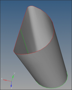
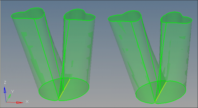
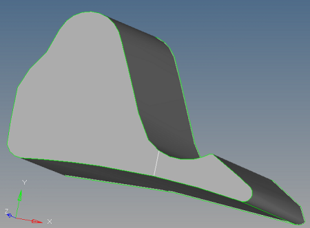
| 11. | Zoom into the area indicated in the following image. |
| 12. | Click on the edge in red color and click create. Notice that a surface is created, making Manifold0 an enclosed volume. |
| 13. | Click solids on the main menu. Select all the surfaces and click create to create the solids. |
|
| 1. | Hide Manifold0 and show Manifold1 and make it current by following step 6 above. |
| 2. | Press F5 to open the Mask panel. |
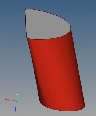
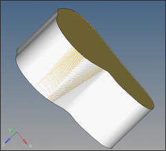
| 3. | Change the entity type to surfs. Select one half of the Manifold1 and click mask to hide that part. |
| 5. | In the main menu, click delete to open the Delete panel. |
| 6. | Change the entity type to surfs. |
| 7. | Select the surface shown in the image below and click delete entity. |
| 9. | Click surfaces on the main menu to open the Surfaces panel. |
| 10. | Make sure the entity type is set to lines. |
| 11. | Select Auto create (free edges only) and clear Keep tangency. Click on the free edges (red). Notice that the surface is created. |
| 12. | Press F5 and click on unmask all. |
| 13. | Repeat steps 3-11 to delete and create the corresponding surface on the other half of Manifold1. |
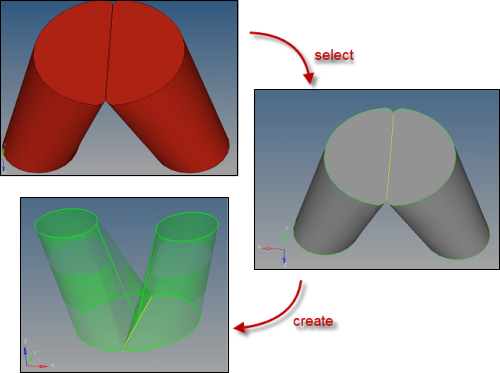
| 14. | Click edge edit on the main menu. |
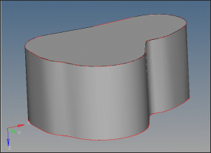
| 15. | Select the replace radio button. |
| 16. | Replace one of the lines with the other line by properly selecting the moved edge and retained edge. If necessary increase the tolerance to 0.6. After this step a shared edge (yellow) will be created between the two parts. |
| 18. | Click solids on the main menu. Select all the surfaces and click create to create the solids. |
|
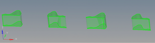
| 1. | Hide Manifold1 and show only Manifold2 and make it current by following step 6 above. |
| 2. | Rotate the geometry and notice the two missing surfaces. |
| 3. | Click surfaces on the main menu. |
| 4. | Make sure the entity type is set to lines. Select the Auto create (free edges only) option. |
| 5. | Clear Keep tangency. Click on the free edges (red). |
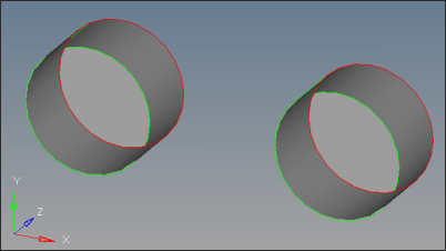
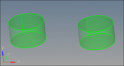
| 6. | Notice that the surfaces are created. Click return. |
| 7. | Click solids on the main menu. Select all the surfaces and click create to create the solids. |
Now Manifold0, Manifold1 and Manifold2 are clean. The next step is to clean Manifold3.
|
| 1. | Hide Manifold2 and show only Manifold3 and make it current by following step 6 above. |
| 2. | Click edge edit on the main menu and notice that there are several geometry errors. |
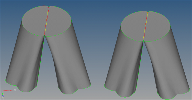
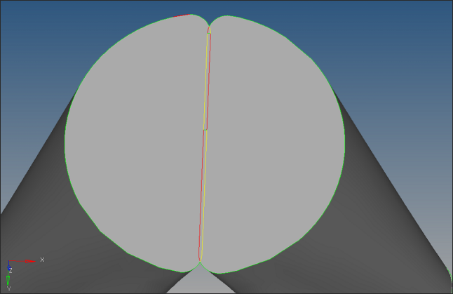
| 3. | Clean one of the two sub parts at a time, starting with the right side part. |
Zoom into the region shown below. Click replace on the Edge Edit panel to move the right side line on to the left side line.
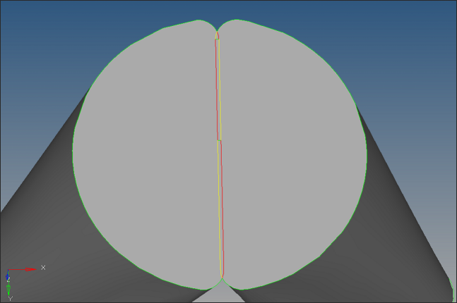
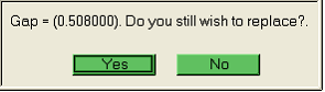
| 4. | The gap is about 0.5 between the lines. Click yes if the following window shows up. |
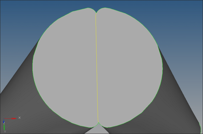
| 5. | Carefully select the lines for moved edge and retained edge such that surfaces on both sides share at a single edge as shown in the picture below. |
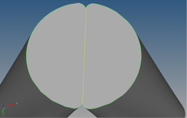
| 6. | Now clean up the left side part. Zoom into the region shown below. |
Use the replace option on the Edge Edit panel to move the left side line on to the right side line such that surfaces on both sides share at a single edge as shown in the picture below.
| 7. | Still there are geometry errors in top region. Zoom into that region. |
| 8. | Select the equivalence radio button and click the equiv free edges only check box. |
| 9. | Select the outside line and click equivalence. Those two lines will be equivalenced. |
Now Manifold3 is completely clean.
| 10. | Click solids on the main menu. Select all the surfaces and click create to create the solids. |
|
| 1. | Hide all the components and show only Manifold4 and make it current by following step 6 above. |
| 2. | Click edge edit on the main menu to observe the geometry errors. |
| 3. | Notice that except one part all the parts are already clean. |
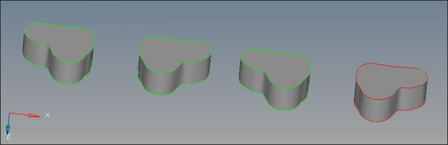
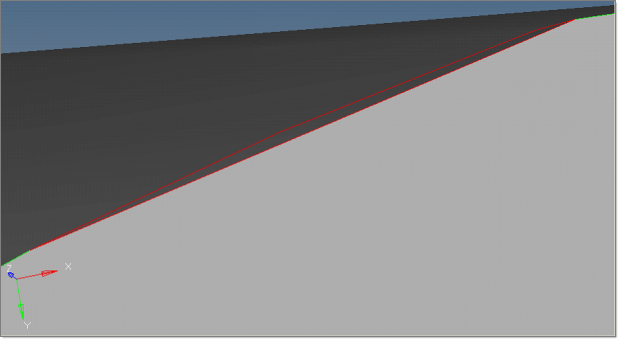
| 4. | Zoom in the region where corrections are necessary. |
| 5. | Observe that red and green lines are overlapped on the outer edges. This indicates a possible duplicate surface. |
| 6. | Click return to exit the Edge Edit panel. |
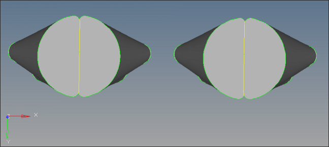
| 7. | Click delete on the main menu. Select the outer surface as shown in the picture below. Click delete entity. The duplicate surface will be deleted. |
| 8. | Some errors still persist. Delete the two surfaces as shown in the picture below and recreate them. This will completely clean Manifold4. |
| 9. | Click solids on the main menu. Select all the surfaces and click create to create the solids. |
|
| 1. | Observe that there are no errors in Manifold5 geometry. |
| 2. | Click solids on the main menu. Select all the surfaces and click create to create the solids. |
| 3. | Manifold6 geometry is also clean except one unwanted edge. Suppress that edge using the suppress option on the Edge Edit panel. |
| 4. | Click solids on the main menu. Select all the surfaces and click create to create the solids. |
| 5. | Click translate on main panel. |
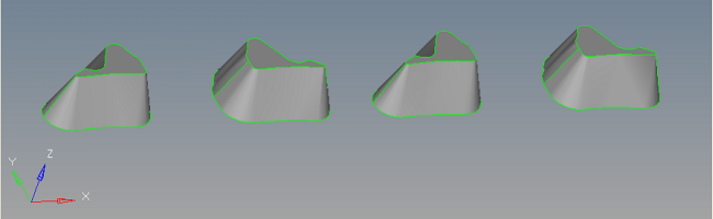
| 6. | Change the entity selector to comps. Change the direction to y-axis and magnitude to 100.00. Select collectors, manifold0, Manifold2, Manifold4, Manifold6 and click translate-. All the components will be aligned. |
|
Return to Polymer Processing Tutorials